
The Shift from TCS3200 to TCS34725 in Modern Prototyping
If you have browsed older electronics forums, you have likely seen the TCS3200 color sensor module. While it was a staple for years, the maker community has largely migrated to the TCS34725 for professional and reliable hobbyist projects. Interfacing a color sensor with Arduino using the TCS34725 eliminates the need for complex timer interrupts and frequency-to-color math. Instead, it utilizes a standard I2C bus, an integrated IR-blocking filter, and a built-in LED driver for consistent illumination.
As of 2026, the TCS34725 is the undisputed standard for colorimetry in DIY sorting machines, liquid analysis, and ambient light matching. In this tutorial, we will cover the exact hardware requirements, the physics of integration time, and the mathematical traps beginners fall into when converting raw sensor data to usable RGB hex codes.
Hardware Requirements and 2026 Pricing
Before wiring, you need to source the correct breakout board. The market currently offers two main tiers:
- Premium Breakouts (e.g., Adafruit 1334): Priced around $11.95. These include 3.3V voltage regulation, I2C pull-up resistors, and a properly diffused onboard LED. Highly recommended for 3.3V microcontrollers like the ESP32 or Arduino Nano 33 IoT.
- Generic Clone Modules: Priced between $3.00 and $4.50 on Amazon or AliExpress. These often lack the 3.3V LDO regulator and require you to manually manage I2C pull-ups if your Arduino does not have internal ones enabled. They are perfectly fine for 5V Arduino Uno R3 or R4 projects.
Complete Bill of Materials (BOM)
| Component | Specification | Estimated Cost |
|---|---|---|
| Microcontroller | Arduino Uno R4 Minima or R3 | $27.60 / $15.00 |
| Color Sensor | TCS34725 I2C Breakout | $3.50 - $11.95 |
| Jumper Wires | F-to-F and M-to-F (22 AWG silicone) | $4.00 |
| Diffuser (Optional) | Ping pong ball or frosted acrylic (1mm) | $1.00 |
Pinout and I2C Wiring Matrix
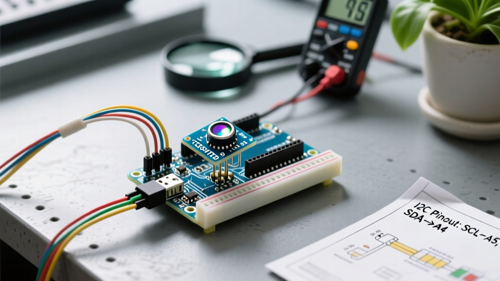
The TCS34725 communicates via I2C, meaning it only requires two data lines regardless of how many sensors you daisy-chain (though the default I2C address is 0x29). Below is the exact wiring matrix for an Arduino Uno R3/R4.
| TCS34725 Pin | Arduino Uno Pin | Function & Notes |
|---|---|---|
| VIN | 5V | Power input. Use 3.3V if on a 3.3V native board. |
| GND | GND | Common ground. Essential for I2C stability. |
| SCL | A5 | I2C Clock line. |
| SDA | A4 | I2C Data line. |
| INT | Pin 2 | Interrupt pin (Optional, for low-power sleep modes). |
| LED | 5V or GPIO | Tie to 5V for always-on, or use a GPIO to toggle. |
Expert Tip: If you are using a generic clone module and experiencing I2C timeout errors, your board likely lacks pull-up resistors on the SDA and SCL lines. You will need to solder two 4.7kΩ resistors between the SDA/SCL lines and the VIN pin. Premium boards like those from Adafruit include these on the PCB by default.
Configuring Integration Time and Gain (The Secret to Accuracy)
Most beginner tutorials skip the internal configuration of the TCS34725, relying on default library settings. This is a critical mistake. The sensor's accuracy depends entirely on matching the Integration Time and Gain to your specific ambient lighting environment.
Understanding Integration Time
Integration time dictates how long the sensor's photodiodes collect light before converting it to a digital value. Longer times yield higher resolution but slower refresh rates.
- 2.4ms (Register 0xFF): Best for extremely bright, direct sunlight or high-speed conveyor sorting.
- 50ms (Register 0xEB): The sweet spot for indoor desk lighting and standard LED ring illumination.
- 700ms (Register 0x00): Maximum resolution, used for low-light environments or analyzing highly translucent, dark liquids.
Setting the Gain Multiplier
Gain amplifies the analog signal before the ADC converts it. The TCS34725 supports 1x, 4x, 16x, and 60x gain. Never use 60x gain in a room with standard overhead lighting; the sensor will saturate (max out at 65535), rendering all colors as blinding white. Start with 1x or 4x gain, and only increase to 16x if your raw 'Clear' channel reads below 1000.
Arduino Code: Raw Data to Calibrated RGB Hex
To interface the color sensor with Arduino, we utilize the standard Wire library for I2C communication. For a deeper understanding of the I2C protocol mechanics, refer to the Arduino Wire Reference and the official NXP I2C Bus Specification.
Below is a production-ready code snippet. Notice that we do not use the map() function to convert raw values to RGB. Raw values fluctuate based on distance and ambient light. Instead, we use ratio-based calibration against the Clear (C) channel.
#include <Wire.h>
#include <Adafruit_TCS34725.h>

// Initialize with 50ms integration time and 4x gain
Adafruit_TCS34725 tcs = Adafruit_TCS34725(TCS34725_INTEGRATIONTIME_50MS, TCS34725_GAIN_4X);

void setup() {
  Serial.begin(115200);
  if (!tcs.begin()) {
    Serial.println("I2C Error: TCS34725 not found. Check SDA/SCL wiring.");
    while (1) delay(10);
  }
  Serial.println("Sensor initialized. Place object 1cm from lens.");
}

void loop() {
  float red, green, blue;
  uint16_t r, g, b, c, colorTemp, lux;

  tcs.getRawData(&r, &g, &b, &c);

  // Prevent division by zero if sensor is covered
  if (c == 0) c = 1;

  // Ratio-based RGB calculation (Information Gain: bypasses ambient light shifts)
  red = (float)r / (float)c * 255.0;
  green = (float)g / (float)c * 255.0;
  blue = (float)b / (float)c * 255.0;

  // Clamp values to 0-255
  if (red > 255) red = 255;
  if (green > 255) green = 255;
  if (blue > 255) blue = 255;

  Serial.print("RGB: ");
  Serial.print((int)red); Serial.print(", ");
  Serial.print((int)green); Serial.print(", ");
  Serial.println((int)blue);

  delay(500);
}
Real-World Troubleshooting and Edge Cases
When building color-sorting peripherals, hardware integration is only half the battle. Environmental factors heavily influence photodiode arrays. Use this troubleshooting matrix to diagnose common field failures.
| Symptom | Root Cause | Engineering Solution |
|---|---|---|
| All colors read as 255, 255, 255 | Sensor saturation due to high gain or intense IR/ambient light. | Drop gain to 1x. Ensure the onboard IR-blocking filter is not scratched off. Add a physical shroud. |
| Readings fluctuate wildly by 20%+ | Specular reflection (glare) from shiny objects hitting the photodiodes unevenly. | Place a 1mm frosted acrylic diffuser over the sensor aperture, or angle the sensor 15 degrees off-axis. |
| I2C Timeout / Sensor not found | Missing pull-up resistors on SDA/SCL lines, or voltage mismatch. | Add 4.7kΩ pull-ups to VCC. Verify logic level shifting if using a 3.3V sensor on a 5V Arduino. |
| Dark colors read as pure black | Integration time too short; photons not accumulating sufficiently. | Increase integration time to 154ms (Register 0xC0) and bump gain to 16x. |
The Distance Sweet Spot
The TCS34725 lacks a focusing lens; it relies on a raw aperture. The optimal focal distance for reading opaque, matte surfaces is exactly 10mm to 15mm. If you place the object closer than 5mm, the LED illumination will bounce off the surface and blind the sensor with localized hotspots. If you place it further than 30mm, ambient room light will dilute the color accuracy. For automated sorting projects, use a 3D-printed jig to physically constrain the object's Z-axis distance to exactly 12mm.
Next Steps for Peripheral Interfacing
Once you have mastered stable RGB extraction, the next logical step in your peripheral journey is integrating this data into a closed-loop control system. Feed the calibrated hex values into a PID controller to adjust a NeoPixel ring, or use the data to trigger a servo-driven sorting gate via a PCA9685 PWM driver. Understanding the physics of light capture and I2C timing transforms a basic color sensor from a novelty toy into an industrial-grade inspection tool.