
Understanding the Arduino FSR Sensor
Force Sensitive Resistors (FSRs) are passive, variable-resistance components that decrease in electrical resistance as physical pressure is applied to their active surface. Unlike precision load cells that require complex HX711 amplifier circuits, an Arduino FSR sensor setup is remarkably straightforward, making it the ideal entry point for beginners exploring physical computing, wearable tech, and interactive art installations.
However, the simplicity of wiring an FSR often masks the complexity of interpreting its data. FSRs are inherently non-linear, prone to mechanical hysteresis, and sensitive to environmental factors. This comprehensive 2026 tutorial moves beyond basic 'hello world' blinking LEDs to provide a robust, production-ready framework for integrating FSRs into your microcontroller projects.
Hardware Selection and 2026 Pricing
Before writing code, you must select the right sensor for your mechanical constraints. The market is dominated by a few key players, and pricing has stabilized in 2026 due to mature manufacturing processes.
- Interlink 402 Series (e.g., 402, 406): The industry standard. The 1.5-inch square model (Interlink 406) typically costs between $7.00 and $9.50 USD. It offers a force range of 100g to 10kg and excellent repeatability.
- Adafruit / SparkFun Branded FSRs: Often rebranded Interlink or similar OEM sensors. Adafruit's 1.5" square FSR (Product ID 166) retails for $8.95. They are ideal for breadboard prototyping due to their standardized 0.1" pitch connectors.
- Velostat / Linqstat: A carbon-impregnated polyolefin film. While not a true FSR, it is often used as a DIY alternative for large-area pressure mats. It costs roughly $15.00 per square foot, but suffers from severe temperature drift and high baseline conductivity.
Pro-Tip: Never solder directly to the exposed silver traces of an FSR. The heat will melt the polymer substrate and destroy the sensor. Always use a ZIF connector, conductive tape, or crimp connectors for termination.
The Voltage Divider Circuit
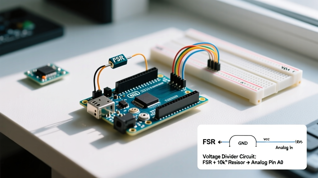
An Arduino cannot read resistance directly; its Analog-to-Digital Converter (ADC) measures voltage (0V to 5V on a standard Uno). To translate the FSR's changing resistance into a readable voltage, we must build a voltage divider using a fixed pull-down resistor.
Calculating the Pull-Down Resistor
The standard beginner tutorial will tell you to grab a 10kΩ resistor. While 10kΩ works for general purposes, it is rarely optimal for your specific force range. The output voltage ($V_{out}$) is calculated as:
V_{out} = V_{in} \times \frac{R_{pull}}{R_{fsr} + R_{pull}}
To maximize the ADC resolution across your target force range, the pull-down resistor ($R_{pull}$) should ideally match the geometric mean of the FSR's minimum and maximum resistance. For an Interlink 406, resistance ranges from ~250Ω (at 10kg) to >1MΩ (at rest). The geometric mean is roughly 15kΩ, making a 10kΩ or 15kΩ resistor the mathematically optimal choice for a full-range 0-10kg application.
If your project only measures heavy forces (e.g., a drum pad triggering at >2kg), the FSR resistance will drop below 1kΩ. In this case, swapping to a 1kΩ or 3.3kΩ pull-down resistor will dramatically improve your voltage resolution at the high-force end of the curve.
Step-by-Step Wiring Guide
- Connect one leg of the 10kΩ pull-down resistor to the Arduino's GND pin.
- Connect one pin of the FSR to the Arduino's 5V pin (or 3.3V if using a 3.3V logic board like the ESP32 or Arduino Nano 33 IoT).
- Connect the second pin of the FSR to the second leg of the 10kΩ resistor. This junction is your signal node.
- Run a jumper wire from this signal junction to the Arduino's A0 (Analog Input 0) pin.
For a deeper dive into basic analog inputs, refer to the official Arduino AnalogInOutSerial documentation.
Arduino Code: Reading and Scaling
Because the FSR's resistance drops logarithmically as force increases, a raw analogRead() will yield highly non-linear data. The code below implements a basic piecewise-linear approximation to map the raw ADC values into a more usable 0-100 'pressure' scale.
// Arduino FSR Sensor Interfacing Code
const int fsrPin = A0;
int fsrReading;
int pressureLevel;

void setup() {
  Serial.begin(115200);
  pinMode(fsrPin, INPUT);
}

void loop() {
  fsrReading = analogRead(fsrPin);

  // Piecewise linear approximation for Interlink 402/406 with 10k pull-down
  if (fsrReading < 15) {
    pressureLevel = 0; // No force (noise floor)
  } else if (fsrReading < 150) {
    pressureLevel = map(fsrReading, 15, 150, 1, 20); // Light touch
  } else if (fsrReading < 600) {
    pressureLevel = map(fsrReading, 150, 600, 20, 80); // Medium squeeze
  } else {
    pressureLevel = map(fsrReading, 600, 1023, 80, 100); // Heavy press
  }

  Serial.print("Raw ADC: ");
  Serial.print(fsrReading);
  Serial.print(" | Scaled Pressure: ");
  Serial.println(pressureLevel);

  delay(50); // 20Hz sampling rate is sufficient for most human-interaction FSRs
}
For advanced users requiring precise Newton (N) measurements, you must implement a logarithmic regression formula in C++ or offload the math to a Python script via serial communication. The Adafruit FSR Guide provides excellent baseline code for logarithmic force approximation.
Force vs. Resistance vs. Voltage Data Matrix
Understanding the relationship between physical force, sensor resistance, and the resulting ADC voltage is critical for calibrating your thresholds. The table below maps these values for a standard Interlink FSR using a 5V supply and a 10kΩ pull-down resistor.
| Applied Force | Approx. Mass | FSR Resistance | Voltage at A0 | ADC Value (10-bit) |
|---|---|---|---|---|
| No Force | 0 g | > 1 MΩ | ~ 0.05 V | 0 - 10 |
| 0.1 N | ~ 10 g | ~ 60 kΩ | 0.71 V | ~ 145 |
| 1.0 N | ~ 100 g | ~ 10 kΩ | 2.50 V | ~ 512 |
| 10.0 N | ~ 1 kg | ~ 1.5 kΩ | 4.35 V | ~ 890 |
| 100.0 N | ~ 10 kg | ~ 250 Ω | 4.88 V | ~ 999 |
Notice how the ADC value jumps rapidly between 0.1N and 1.0N, but barely moves between 10N and 100N. This visualizes the non-linear nature of the sensor and explains why a simple map() function from 0-1023 fails in real-world applications.
Real-World Troubleshooting and Edge Cases
When moving from a breadboard prototype to a deployed installation, beginners frequently encounter three major physical edge cases:
1. Mechanical Creep
If you apply a constant 5N weight to an FSR and monitor the serial plotter, the voltage will not remain static. The polymer materials inside the sensor exhibit 'creep'—a gradual decrease in resistance over time under a constant load. Expect a 5% to 10% drift in the first 3 to 5 minutes. Solution: Do not use FSRs for continuous static weighing (like a bathroom scale). Use them for dynamic, transient event detection (like a piano key or button press).
2. Hysteresis
The electrical path when pressing down on the sensor is slightly different from the path when releasing the pressure. If you press to 5N and release to 2N, the resistance reading will be slightly higher than if you started at 0N and pressed up to 2N. Solution: Implement a software deadband or hysteresis loop in your code to prevent state-fluttering when triggering digital events.
3. Shear Force Damage
FSRs are designed exclusively for perpendicular, compressive force. Sliding an object across the sensor surface (shear force) will delaminate the internal conductive polymer layers, permanently ruining the sensor. Solution: Always mount the FSR beneath a smooth, rigid mechanical cap (like a 3D printed PLA button) that translates lateral friction into pure downward compression.
Further Reading and Authoritative References
To deepen your understanding of sensor integration and material science, consult the following resources:
- SparkFun FSR Hookup Guide and Integration Notes - Excellent mechanical mounting advice and circuit protection tips.
- Interlink Electronics FSR Overview - The manufacturer's official datasheets, integration guides, and material specifications.
By mastering the voltage divider math, implementing piecewise-linear code scaling, and designing enclosures that mitigate shear force, your Arduino FSR sensor projects will transition from fragile prototypes to reliable, production-grade interfaces.