
The Multi-Peripheral Challenge: Adding a Servo with Arduino
Building a complex robotics or automation project in 2026 rarely involves just a single component. When you combine environmental sensors (like the BME680), SPI-based TFT displays, and UART GPS modules on a single microcontroller, adding a servo with Arduino introduces a unique set of electrical and architectural challenges. While a basic blink-and-sweep tutorial works on an empty breadboard, real-world multi-peripheral setups frequently fail due to power starvation, I2C bus noise, and PWM signal jitter.
This guide moves beyond beginner tutorials. We will explore the exact power topologies, I2C multiplexing strategies, and signal integrity techniques required to reliably drive high-torque servos alongside sensitive sensor arrays without triggering ATmega328P or ESP32 brownout resets.
The Power Bottleneck: Why Direct Wiring Fails
The most common point of failure in multi-peripheral builds is attempting to power a servo directly from the Arduino’s onboard 5V pin. The onboard linear regulator (typically an NCP1117 or similar LDO) is designed to supply a maximum of 500mA to 800mA. However, the moment a servo motor encounters mechanical resistance, its current draw spikes dramatically.
Expert Insight: A standard micro servo might draw 200mA at idle, but its stall current can easily exceed 700mA. If your OLED display and I2C sensors are already consuming 150mA, engaging the servo will instantly collapse the 5V rail, causing the microcontroller to reset or behave erratically.
2026 Servo Selection & Current Draw Matrix
Choosing the right actuator is critical when balancing a shared power budget. Below is a comparison of common servos used in advanced DIY builds, including their real-world stall currents and approximate 2026 market pricing.
| Model | Gear Type | Torque (at 6V) | Stall Current | Ideal Use Case | Avg. Price |
|---|---|---|---|---|---|
| TowerPro SG90 | Plastic | 1.8 kg-cm | ~700 mA | Lightweight pan/tilt camera mounts | $2.50 |
| MG90S | Metal | 2.2 kg-cm | ~850 mA | Small robotic joints, RC aircraft | $4.00 |
| MG996R | Metal | 13.0 kg-cm | ~2.5 A | Robotic arms, heavy-duty steering | $6.50 |
| DS3218 (20kg) | Steel | 20.0 kg-cm | ~3.2 A | Industrial automation, heavy lifting | $14.00 |
Source: Pololu High-Torque Servo Specifications
Architectural Solution: The PCA9685 I2C Servo Driver
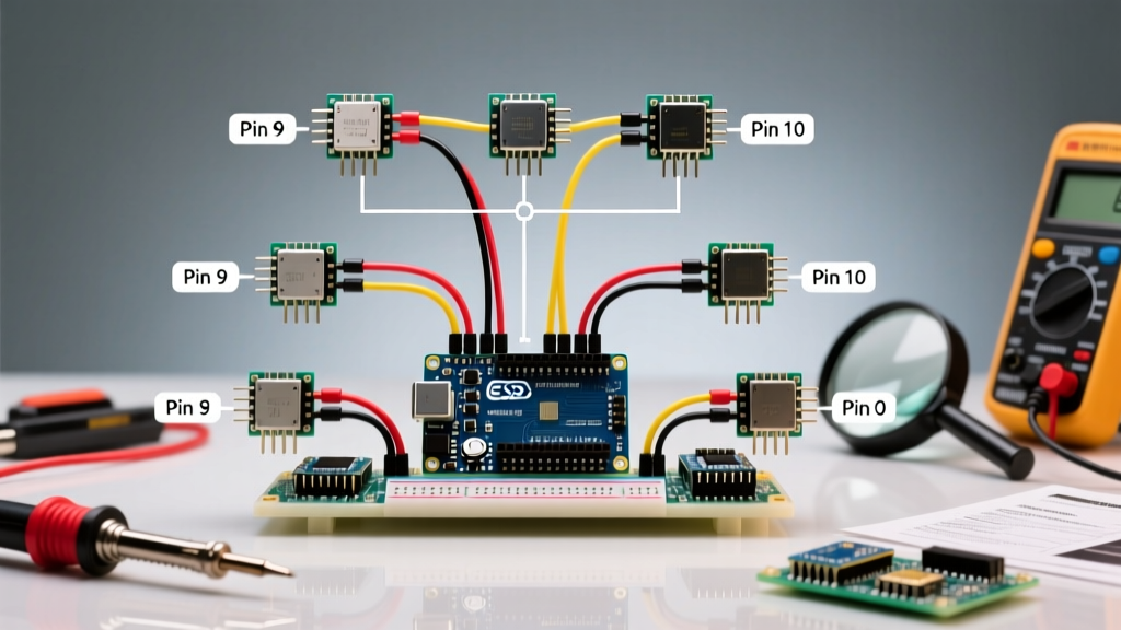
In a multi-peripheral setup, hardware PWM pins are a scarce resource. If your SPI display uses pins 11, 12, and 13, and your hardware serial UART uses pins 0 and 1, you quickly run out of native PWM-capable pins for servos. Furthermore, the native Arduino Servo library disables PWM on pins 9 and 10 when active, which can break motor shields or LED fading routines.
The industry-standard solution is the PCA9685 16-Channel PWM Driver. Priced around $3 to $5, this breakout board communicates via I2C, freeing up your microcontroller’s GPIO pins while providing hardware-timed, jitter-free PWM signals.
- Pin Conservation: Uses only 2 pins (SDA/SCL) to control up to 16 servos.
- Jitter Elimination: The PCA9685 handles the PWM timing internally, meaning I2C interrupts from your BME680 sensor won’t cause your servo to twitch.
- Addressability: By cutting specific solder jumpers, you can chain up to 62 boards on a single I2C bus.
For comprehensive wiring and library implementation, refer to the Adafruit 16-Channel PWM Servo Driver Guide.
Step-by-Step Multi-Peripheral Wiring Strategy
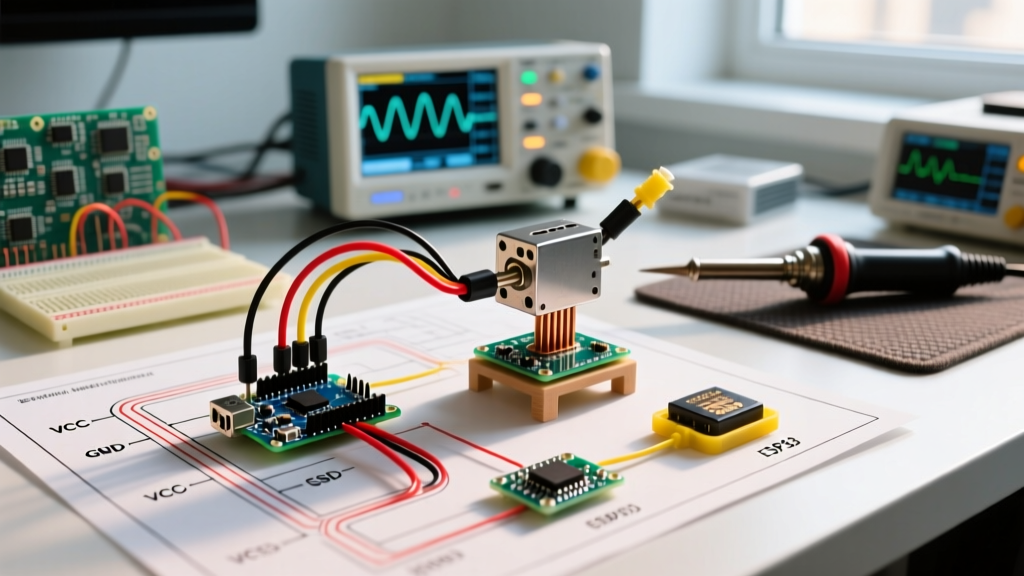
To integrate a high-torque servo like the MG996R alongside sensitive I2C sensors, you must isolate the high-current actuator power from the low-noise logic power. Follow this exact topology:
Step 1: Implement a Dedicated Buck Converter
Do not use a linear regulator (like the L7805) for servos; they waste too much energy as heat. Instead, use a switching buck converter (e.g., LM2596 or a Pololu D24V50F5) to step down your main battery voltage (e.g., 12V LiPo) to a stable 5V. Ensure the converter is rated for at least 5A continuous output to handle the stall current of large servos.
Step 2: Establish a Common Ground
This is the most frequently missed step. The ground (GND) of your external 5V servo power supply must be connected to the GND pin of your Arduino. Without a common ground reference, the PWM signal from the microcontroller has no baseline, resulting in a servo that spins wildly or fails to move.
Step 3: Deploy Decoupling Capacitors
Servos are inductive loads. When they start and stop, they send voltage spikes back through the power rails, which can corrupt data on your I2C sensor bus.
- Solder a 1000µF electrolytic capacitor directly across the main 5V and GND power rails near the servo.
- Place a 100nF (0.1µF) ceramic capacitor as close to the servo’s power pins as possible to filter high-frequency noise.
Step 4: Wire Gauge Selection
Voltage drop over thin wires will starve your servo. Use 18 AWG silicone wire for the 5V and GND power rails. You can use standard 22 AWG jumper wires for the PWM signal lines, as they carry negligible current.
Software Optimization: Mitigating Jitter and Idle Draw
When using the official Arduino Servo Library Documentation, a common oversight is leaving the servo attached after it reaches its target position. A continuous PWM signal keeps the servo’s internal potentiometer circuit active, drawing idle current and generating low-level electrical noise.
Actionable Code Pattern:
#include <Servo.h>
Servo myServo;

void moveToPosition(int targetAngle) {
  myServo.attach(9);
  myServo.write(targetAngle);
  delay(500); // Allow time to reach position
  myServo.detach(); // Cuts PWM signal, saves power, reduces noise
}
By utilizing the detach() function immediately after the movement is complete, you eliminate idle current draw and remove a massive source of PWM noise from your multi-peripheral environment.
Troubleshooting Multi-Peripheral Conflicts
Even with perfect wiring, mixing high-current actuators and sensitive digital buses can cause edge-case failures. Use this diagnostic matrix to resolve common issues.
| Symptom | Root Cause | Engineering Solution |
|---|---|---|
| Arduino randomly resets when servo moves. | Brownout due to voltage sag on the 5V logic rail. | Separate the servo power supply from the Arduino logic power. Add a 1000µF bulk capacitor. |
| I2C sensors (e.g., OLED, BME280) drop offline. | Inductive spikes from the servo corrupting the I2C SDA/SCL lines. | Add 4.7kΩ pull-up resistors to SDA/SCL. Use twisted-pair wiring for I2C lines. |
| Servo twitches or jitters continuously. | Software PWM interrupt conflicts or noisy power. | Switch to a hardware PCA9685 driver. Ensure common ground between MCU and servo PSU. |
| Servo hums but does not move under load. | Voltage drop across thin wires or breadboard traces. | Upgrade to 18 AWG wire. Avoid routing high-current servo power through breadboard rails. |
Summary: Best Practices for Complex Builds
Successfully integrating a servo with Arduino in a dense, multi-peripheral environment requires treating power and signal integrity as first-class design constraints. By offloading PWM generation to an I2C PCA9685 driver, isolating high-current actuator power via a switching buck converter, and aggressively filtering inductive noise with decoupling capacitors, you ensure that your sensors, displays, and motors operate in perfect harmony. Always prioritize heavy-gauge wiring for power rails and implement software-level detach routines to maintain a clean electrical environment.