
The Bridge Between Logic and Mains: Understanding the Arduino 5V Relay
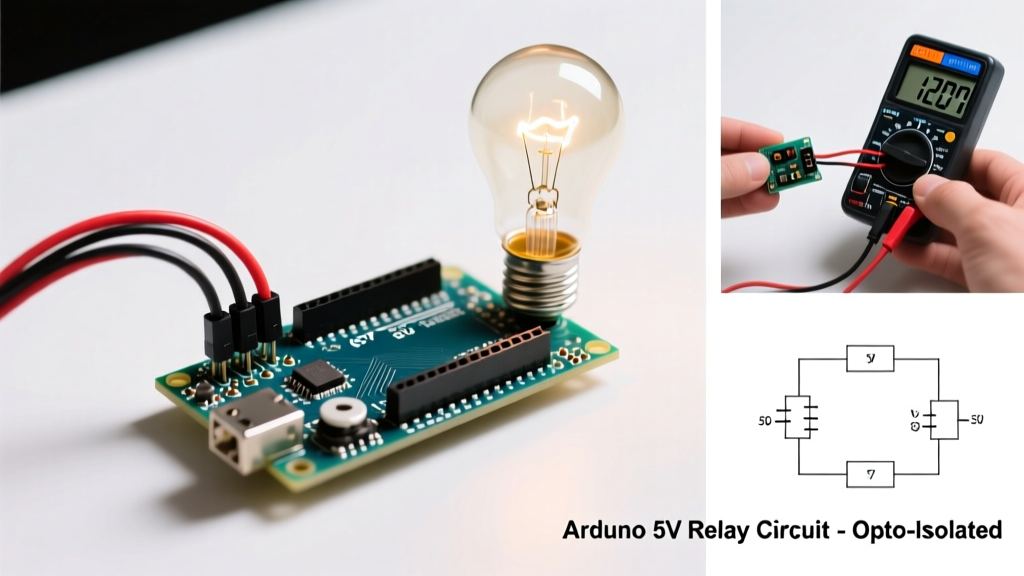
In the realm of microcontroller peripherals, few components are as ubiquitous—and as frequently misunderstood—as the standard Arduino 5V relay module. Typically priced between $2.00 and $4.50 in 2026, these modules serve as the critical bridge between the safe, low-voltage 5V DC logic of an ATmega328P or ESP32 and the high-voltage 120V/240V AC mains required to drive real-world loads like greenhouse exhaust fans, sump pumps, and space heaters.
However, treating a mechanical relay module as a simple 'on/off switch' is a fast track to fried microcontrollers, welded contacts, and potential fire hazards. According to the Arduino Official Relay Guide, improper isolation and failure to account for inductive kickback are the leading causes of peripheral failure in DIY automation. This guide moves beyond basic blinking LEDs, diving deep into the electrical realities, safety modifications, and fail-safe coding architectures required for deploying an Arduino 5V relay in permanent, real-world applications.
Anatomy of the Standard Blue Cube Module
To master the Arduino 5V relay, you must first understand the four distinct sub-circuits packed onto the standard 50mm x 25mm PCB:
- The Mechanical Relay: Usually a Songle SRD-05VDC-SL-C. Rated for 10A at 250VAC or 30VDC. It contains a physical copper coil and spring-loaded contacts (Common, Normally Open, Normally Closed).
- The Optocoupler: A PC817 chip that uses light to transmit the trigger signal across an internal gap, theoretically providing galvanic isolation between your Arduino and the relay coil.
- The Drive Transistor: Typically an S8050 NPN bipolar junction transistor (BJT) that amplifies the tiny current from the optocoupler to drive the 70mA required by the relay coil.
- The Flyback Diode: A 1N4007 diode wired in reverse bias across the relay coil to safely dissipate the inductive voltage spike generated when the coil's magnetic field collapses.
The JD-VCC Jumper: Unlocking True Optical Isolation
Most online tutorials gloss over the small yellow jumper cap labeled JD-VCC located on the corner of the module. Leaving this jumper in place is the single biggest mistake beginners make when wiring an Arduino 5V relay for mains control.
Expert Insight: When the JD-VCC jumper is installed, the relay coil and the optocoupler's internal LED share the same 5V power rail sourced directly from your Arduino. If a high-voltage transient arcs across the relay's internal contacts, it can bypass the optocoupler, travel back through the shared ground, and instantly destroy your Arduino's voltage regulator or MCU.
How to Wire for True Galvanic Isolation
To achieve the isolation the PC817 optocoupler was designed for, you must power the relay coil from a separate 5V source (like a dedicated USB buck converter or a secondary 7805 circuit).
- Remove the JD-VCC jumper cap.
- Connect the module's VCC pin to the Arduino's 5V output (this powers the optocoupler LED side).
- Connect the module's GND pin to the Arduino's GND (completing the optocoupler LED circuit).
- Connect your external 5V supply's positive terminal to the JD-VCC pin.
- Connect your external 5V supply's ground to the module's GND pin (or the dedicated relay ground if the board has a split ground plane).
This configuration ensures that the high-current coil switching and any resulting electromagnetic interference (EMI) remain entirely confined to the external power supply, keeping your microcontroller's logic rail pristine.
Real-World Scenario: Automating a 120V AC Greenhouse Exhaust Fan
Let's apply this to a practical scenario: automating a 120V AC, 1/4 HP greenhouse exhaust fan based on temperature thresholds. An exhaust fan motor is an inductive load. Unlike a resistive load (like an incandescent bulb), an inductive load resists changes in current. When the relay contacts open to turn off the motor, the collapsing magnetic field in the motor generates a massive voltage spike (inductive kickback) that can arc across the relay's physical contacts.
Wiring Matrix: Arduino to Relay to Mains
| Source | Terminal | Destination | Wire Gauge / Note |
|---|---|---|---|
| Arduino Uno R3 | Digital Pin 8 | Relay Module IN | 22 AWG solid core |
| Arduino Uno R3 | 5V Pin | Relay Module VCC | 22 AWG (Opto LED power) |
| Arduino Uno R3 | GND Pin | Relay Module GND | 22 AWG (Logic ground) |
| External 5V PSU | Positive (+) | Relay Module JD-VCC | 20 AWG (Coil power) |
| External 5V PSU | Negative (-) | Relay Module GND | 20 AWG (Coil ground) |
| Mains 120V AC | Hot (Line) | Relay COM (Common) | 14 AWG stranded (Mains rated) |
| Relay Module | NO (Normally Open) | Fan Motor Hot | 14 AWG stranded |
| Mains 120V AC | Neutral | Fan Motor Neutral | 14 AWG stranded (Bypasses relay) |
The Hidden Danger: Creepage, Clearance, and Cheap PCBs
While the PC817 provides electrical isolation, the physical PCB layout of budget Arduino 5V relay modules often fails basic safety standards for creepage and clearance. According to SparkFun's Relay Tutorial and general IPC-2221 PCB design standards, there must be adequate physical distance between high-voltage and low-voltage traces to prevent arcing across the board surface, especially in humid environments like a greenhouse.
On many $2 modules, the 120V AC copper traces on the bottom of the PCB run millimeters away from the 5V DC logic traces. Over time, dust accumulation and humidity can create a conductive path, allowing mains voltage to jump to your Arduino.
The 'Scalpel Modification' for Permanent Installations
For permanent, high-humidity, or high-reliability deployments, perform the scalpel modification:
- Flip the module over and locate the optocoupler.
- Using a sharp hobby knife, carefully scrape away the copper trace and the thin layer of fiberglass beneath it that connects the high-voltage side of the board to the low-voltage side, effectively creating a physical trench (increasing the creepage distance).
- Alternatively, for permanent home automation, abandon the cheap blue modules entirely and opt for DIN-rail mounted relays or Solid State Relays (SSRs) like the Omron G3MB-202P, which offer superior internal potting and isolation.
Inductive Kickback and Contact Welding
If your Arduino 5V relay clicks once and then refuses to turn off the connected motor, you have experienced contact welding. The arc generated by the inductive exhaust fan motor literally melted the internal copper contacts of the Songle relay together. The 1N4007 flyback diode on the module only protects the transistor from the relay's internal coil spike; it does absolutely nothing to protect the relay's external contacts from the motor's spike.
The Fix: You must install a snubber circuit across the motor's terminals or across the relay's COM and NO terminals. A standard AC snubber consists of a 100-ohm, 1/2-watt resistor in series with a 0.1µF, 250VAC X2-rated capacitor. This RC network absorbs the high-frequency voltage transient, preserving your relay contacts for hundreds of thousands of cycles.
Fail-Safe Logic and Boot Chatter Prevention
When designing the firmware for an Arduino 5V relay, you must account for the microcontroller's boot sequence and potential crash states. Most standard relay modules are Active-LOW, meaning the relay engages when the IN pin is pulled to GND (0V) and disengages when the pin is HIGH (5V).
During the first few milliseconds of an Arduino boot, or during a firmware upload (reset), the digital pins float in a high-impedance state. This floating state can cause the optocoupler to trigger randomly, resulting in 'boot chatter'—a rapid clicking that can damage the load or the relay.
The Firmware Solution
Always initialize your relay pins with a pull-up strategy in the very first lines of your setup() function:
const int RELAY_PIN = 8;

void setup() {
  // 1. Set pin HIGH immediately to prevent boot chatter
  digitalWrite(RELAY_PIN, HIGH);
  // 2. Then set as OUTPUT
  pinMode(RELAY_PIN, OUTPUT);

  // Initialize serial, sensors, etc.
  Serial.begin(9600);
}
Furthermore, consider your Fail-Safe State. If you are controlling a greenhouse heater, wire the AC load to the Normally Closed (NC) terminal. If the Arduino loses power or crashes, the relay de-energizes, the contacts fall back to NC, and the heater stays on, preventing your plants from freezing. Conversely, for a water pump, always use the Normally Open (NO) terminal so a system crash defaults to 'off', preventing flooding.
Troubleshooting Real-World Field Failures
Even with perfect wiring, environmental factors and component degradation can cause issues. Use this diagnostic matrix to troubleshoot your Arduino 5V relay deployments in the field.
| Symptom | Root Cause Analysis | Field Solution |
|---|---|---|
| Relay clicks, but load does not turn on. | Voltage drop across the relay contacts due to oxidation, or the load exceeds the 10A rating, causing internal thermal cutoff. | Measure voltage across COM and NO while engaged. If >2V drop, replace the relay. For loads >8A, upgrade to a 30A automotive relay or an SSR. |
| Arduino resets randomly when relay clicks. | Insufficient current from the Arduino's 5V regulator. The 70mA coil draw causes a brownout on the ATmega328P. | Implement the JD-VCC isolation wiring described above, powering the coil from an external 5V 1A buck converter. |
| Relay stays ON after Arduino pin goes HIGH. | Inductive load arc has physically welded the internal contacts together. | Disconnect power immediately. Replace the relay module. Install an RC snubber circuit across the load. |
| Optocoupler LED glows faintly, but relay won't engage. | The Arduino pin is not sourcing enough current to fully saturate the PC817 LED, or the S8050 transistor has degraded. | Verify the IN pin is outputting a solid 0V (Active-LOW). If voltage is >0.5V when triggered, add a 2N2222 transistor buffer stage. |
Final Thoughts on Peripheral Integration
The Arduino 5V relay module is a remarkably capable tool when respected as a high-power electromechanical device rather than a simple logic gate. By implementing true optical isolation via the JD-VCC jumper, respecting creepage distances on the PCB, and protecting your contacts from inductive kickback, you transform a $3 hobbyist component into a robust, industrial-grade switching solution. For deeper insights into managing complex AC loads and solid-state alternatives, refer to the comprehensive Electronics Tutorials Relay Switching Guide. Always prioritize safety, use properly rated enclosures for mains voltage, and test your fail-safe logic before leaving your automated system unattended.