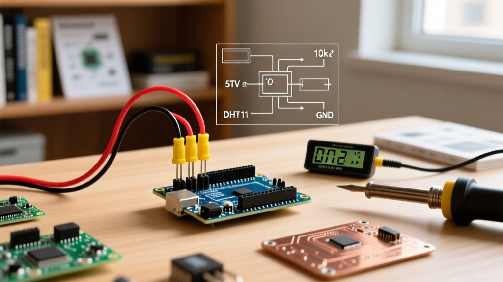

Why the DHT11 Remains a DIY Staple in 2026
Despite the proliferation of advanced I2C environmental sensors, the DHT11 temperature and humidity sensor remains one of the most widely deployed components in the microcontroller ecosystem. For beginners and seasoned makers alike, integrating a sensor DHT11 Arduino setup is a rite of passage. Priced between $1.50 and $2.50 for a fully assembled module in 2026, it offers an accessible entry point into single-bus digital communication protocols.
However, the DHT11 is notorious for frustrating edge cases. Intermittent NaN (Not a Number) readings, silent checksum failures, and self-heating anomalies frequently derail projects. This comprehensive integration tutorial bypasses the basic fluff, diving deep into the hardware realities, microsecond-level timing constraints, and professional troubleshooting frameworks required to build a reliable environmental monitoring node.
DHT11 Hardware Specifications and Limitations
Before writing a single line of C++, you must understand the physical limitations of the DHT11's internal architecture. The module houses a capacitive humidity sensor and an NTC (Negative Temperature Coefficient) thermistor, coupled to an 8-bit microcontroller that handles the analog-to-digital conversion and single-bus framing.
| Parameter | DHT11 Specification | Real-World Implication |
|---|---|---|
| Operating Voltage | 3.3V to 5.5V DC | Directly compatible with 5V (Uno/Mega) and 3.3V (ESP32) logic, though 3.3V requires stricter pull-up tuning. |
| Temperature Range | 0°C to 50°C | Useless for outdoor winter climates or high-heat industrial enclosures. |
| Temperature Accuracy | ±2.0°C | Requires software offset calibration against a reference thermometer for precision applications. |
| Humidity Range | 20% to 90% RH | Condensation or sub-20% environments will yield saturated or invalid data. |
| Sampling Rate | 1 Hz (1 reading/sec) | Polling faster than once per second guarantees data corruption and sensor lockups. |
Pinout and Exact Wiring Configuration
Most hobbyist modules include a 3-pin header with an onboard 5.1kΩ surface-mount pull-up resistor. If you are using the bare 4-pin blue plastic component, you must provide your own external pull-up resistor.
Standard 3-Pin Module Wiring
- VCC (Pin 1): Connect to Arduino 5V (or 3.3V if using an ESP32).
- DATA (Pin 2): Connect to a digital GPIO (e.g., Pin 2). Crucial: If your wire run exceeds 1 meter, add an external 4.7kΩ pull-up resistor between DATA and VCC at the MCU end to combat capacitance-induced signal degradation.
- GND (Pin 3): Connect to Arduino GND.
Understanding the Single-Bus Protocol Timing
The DHT11 does not use I2C or SPI. It relies on a proprietary single-bus (1-Wire style) protocol that is entirely dependent on microsecond-level timing. Understanding this is the key to debugging communication failures.
- Host Start Signal: The Arduino pulls the DATA line LOW for at least 18 milliseconds, then HIGH for 20-40 microseconds.
- Sensor Response: The DHT11 detects the start signal, pulls the line LOW for 80 microseconds, then HIGH for 80 microseconds.
- Data Transmission (40 Bits): The sensor sends 40 bits of data (16-bit Humidity, 16-bit Temperature, 8-bit Checksum). Each bit begins with a 50-microsecond LOW pulse. A HIGH pulse of 26-28 microseconds represents a
0, while a HIGH pulse of 70 microseconds represents a1.
Because this protocol relies on exact microsecond counting, interrupts must be disabled during the read sequence. If a timer interrupt or a software serial routine fires while the Arduino is measuring a 28-microsecond pulse, the bit will be misread, triggering a checksum failure.
Arduino C++ Implementation
While you can write a raw register-level driver, the industry standard for rapid deployment is the Adafruit DHT library. Ensure you have the Adafruit DHT Sensor Library and its dependency, the Adafruit Unified Sensor library, installed via the Arduino IDE Library Manager.
#include "DHT.h"

#define DHTPIN 2     // Digital pin connected to the DHT sensor
#define DHTTYPE DHT11   // DHT 11

DHT dht(DHTPIN, DHTTYPE);

void setup() {
  Serial.begin(115200);
  // DHT11 requires a brief stabilization period on boot
  delay(2000);
  dht.begin();
}

void loop() {
  // CRITICAL: Wait at least 2 seconds between readings.
  // Polling at exactly 1Hz can cause self-heating anomalies.
  delay(2500);

  float h = dht.readHumidity();
  float t = dht.readTemperature(); // Celsius by default

  // Check if any reads failed and exit early (to try again).
  if (isnan(h) || isnan(t)) {
    Serial.println(F("Failed to read from DHT sensor! Checksum or Timing Error."));
    return;
  }

  Serial.print(F("Humidity: "));
  Serial.print(h);
  Serial.print(F("%  Temperature: "));
  Serial.print(t);
  Serial.println(F("°C"));
}
Real-World Failure Modes and Edge Cases
When deploying a sensor DHT11 Arduino circuit in the field, theoretical code often meets physical reality. Here is how to diagnose the most common failure modes:
Pro-Tip: The Self-Heating Trap
The DHT11 draws approximately 1mA to 1.5mA during the active conversion phase. If you poll the sensor continuously in a tightwhile()loop without adequate delays, the internal NTC thermistor will absorb the waste heat from the sensor's own microcontroller. This results in a permanent positive temperature bias of +0.2°C to +0.5°C. Always enforce a minimum 2-second delay between reads.
1. Persistent "NaN" Outputs
If your serial monitor is flooded with NaN errors, the Arduino is failing the checksum validation. The checksum is the sum of the humidity and temperature bytes, masked to 8 bits. If the received checksum doesn't match the calculated one, the library discards the payload and returns NaN.
Fix: Disable competing interrupts. If you are using SoftwareSerial or high-frequency PWM on adjacent pins, pause them before calling dht.readTemperature(). For deeper insights into microcontroller timing conflicts, consult the Arduino Language Reference regarding the noInterrupts() function.
2. The 3.3V Logic Level Mismatch
When interfacing a 5V DHT11 module with a 3.3V microcontroller (like the ESP32 or Raspberry Pi Pico), the 5.1kΩ onboard pull-up resistor pulls the data line up to 5V. This can slowly degrade the 3.3V GPIO over time or cause logic high misinterpretations. Fix: Power the DHT11 VCC pin with 3.3V, or use a bidirectional logic level shifter (e.g., BSS138 MOSFET circuit) on the DATA line.
3. Cable Length and Capacitance
The single-bus protocol is highly susceptible to parasitic capacitance. Standard jumper wires add roughly 10-20pF per foot. Beyond 2 meters, the rise time of the digital signal slows down, turning sharp square waves into sloped ramps. The Arduino's microsecond counter misinterprets the slope, reading a 28us '0' as a 70us '1'. Fix: Use shielded twisted-pair cable for runs over 1 meter, and place a 4.7kΩ pull-up resistor directly at the microcontroller's GPIO pin to provide a stronger current source for charging the line capacitance.
DHT11 vs. Modern Alternatives: A 2026 Comparison Matrix
While the DHT11 is cheap, modern projects often demand better resolution and I2C stability. Below is a comparison to help you decide if the DHT11 is truly the right part for your BOM (Bill of Materials).
| Feature | DHT11 | DHT22 (AM2302) | AHT20 (I2C) |
|---|---|---|---|
| Protocol | Single-Bus (Timing critical) | Single-Bus (Timing critical) | I2C (Interrupt-safe, robust) |
| Temp Resolution | 1.0°C | 0.1°C | 0.01°C |
| Temp Accuracy | ±2.0°C | ±0.5°C | ±0.3°C |
| Humidity Accuracy | ±5% RH | ±2% RH | ±2% RH |
| Avg. Module Cost | ~$1.50 | ~$4.50 | ~$2.80 |
| Best Use Case | Educational kits, basic HVAC | Weather stations, greenhouses | IoT nodes, battery-powered dataloggers |
For a deeper dive into upgrading from single-bus sensors to I2C alternatives, the SparkFun Sensor Hookup Guides provide excellent baseline schematics for level-shifting and pull-up calculations.
Summary
Integrating a DHT11 sensor with an Arduino is an exercise in understanding hardware constraints. By respecting the 1Hz polling limit, managing parasitic capacitance on long wire runs, and acknowledging the strict microsecond timing requirements of the single-bus protocol, you can transform this budget component into a reliable environmental monitor. However, if your 2026 project requires sub-zero temperature tracking, high-precision data logging, or interrupt-driven architecture, bypass the DHT11 entirely and design around an I2C-native sensor like the AHT20.