
The Physics of Stepper Motor Inaccuracy
When building precision motion systems for CNC routers, 3D printers, or automated lab equipment, pairing a high-quality stepper driver with an Arduino microcontroller is only the first step. Out of the box, most stepper driver Arduino setups suffer from microstepping non-linearity, pulse jitter, and thermal drift. True sub-millimeter accuracy requires a rigorous calibration protocol that bridges the gap between digital logic and electromagnetic physics.
This guide bypasses basic wiring tutorials and dives directly into the advanced calibration techniques required in 2026 for achieving repeatable, high-torque, and jitter-free motion control using AVR and ESP32-based Arduino ecosystems.
Hardware Selection: The 2026 Driver Matrix
Before calibrating, you must understand the silicon limitations of your chosen driver. The market has shifted heavily toward intelligent UART-based drivers, though legacy pulse/direction chips remain relevant for cost-sensitive projects.
| Driver IC | Max Current (RMS) | Microstepping | Interface | Avg. Price (2026) | Best Use Case |
|---|---|---|---|---|---|
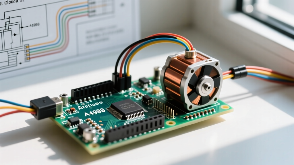
| A4988 | 1.0A (1.5A w/ cooling) | 1/16 | Step/Dir | $1.50 - $2.00 | Basic prototyping, low-cost plotters |
| DRV8825 | 1.5A (2.2A w/ cooling) | 1/32 | Step/Dir | $2.00 - $2.80 | Standard 3D printers, light CNC |
| TMC2209 | 2.0A (2.8A peak) | 1/256 | Step/Dir + UART | $4.00 - $5.50 | Silent operation, sensorless homing |
| TMC5160 | 20A (w/ external FETs) | 1/256 | SPI + Step/Dir | $8.00 - $12.00 | Heavy-duty CNC, industrial robotics |
Phase 1: Precision Current Limiting (Vref Calibration)
The most common cause of missed steps and erratic calibration in a stepper driver Arduino setup is improper current limiting. Relying on 'factory default' potentiometer settings will lead to either thermal shutdown or insufficient holding torque.
Calculating and Measuring Vref
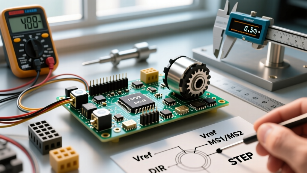
For legacy drivers like the A4988 and DRV8825, current is limited by a reference voltage (Vref) generated by an onboard potentiometer. The formula depends on the sense resistor (Rs) on your specific breakout board.
- Pololu A4988 (Rs = 0.05Ω): Current Limit = Vref × 2.5
- Generic DRV8825 (Rs = 0.1Ω): Current Limit = Vref × 2
Calibration Procedure:
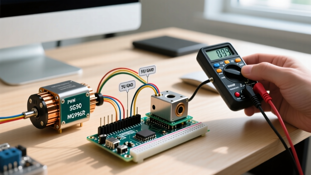
- Power the Arduino and the motor driver's logic side (VDD), but do not connect the high-voltage motor supply (VMOT) yet.
- Set your multimeter to DC Voltage (2V range).
- Place the black probe on a reliable system ground (GND) and the red probe on the metal shaft of the Vref potentiometer.
- Using a ceramic flathead screwdriver, adjust the pot until you hit your target Vref. For a standard NEMA 17 motor rated at 1.5A on a DRV8825, target a Vref of 0.75V.
Expert Warning: Never adjust the Vref potentiometer while the high-voltage motor supply is active. The potentiometer is not isolated, and a slip of the screwdriver can short VMOT to the logic pins, instantly destroying your Arduino's ATmega328P or ESP32.
Phase 2: Microstepping Non-Linearity and Torque Curves
A pervasive myth in the maker community is that 1/16 or 1/32 microstepping proportionally increases positional resolution. In reality, microstepping is primarily a resonance damping technique. As you increase microstep divisions, the incremental holding torque drops drastically.
The Torque Decay Reality
According to electromagnetic principles governing hybrid stepper motors, the incremental torque at a given microstep position is defined by the sine of the electrical angle. At 1/16th microstepping, the holding torque between adjacent microsteps is only about 10% of the motor's full-step rated torque.
If your mechanical system has high stiction or backlash, the motor may 'absorb' several microsteps without physically moving the rotor, resulting in accumulated positional error. To calibrate for accuracy:
- For high-load CNC axes: Limit microstepping to 1/4 or 1/8 to maintain rigid inter-step torque.
- For optical/laser positioning: Use 1/16 or 1/32 microstepping to eliminate low-frequency resonance, but implement closed-loop verification (e.g., linear encoders) to account for microstep absorption.
Phase 3: Arduino Pulse Timing and Jitter Elimination
Sending step pulses via standard Arduino digitalWrite() and delayMicroseconds() functions guarantees positional inaccuracy at high speeds. The Arduino Uno's main loop is susceptible to interrupt jitter from serial communication, sensor polling, and watchdog timers.
Overcoming the 4kHz AVR Bottleneck
When using the industry-standard AccelStepper library on an 8-bit AVR Arduino (like the Uno or Nano), the maximum reliable step rate is approximately 4,000 steps per second. Beyond this, the library's blocking acceleration calculations cause pulse timing jitter, leading to audible motor ringing and missed steps.
Solutions for Jitter-Free Timing:
- Hardware Timers (AVR): Use the
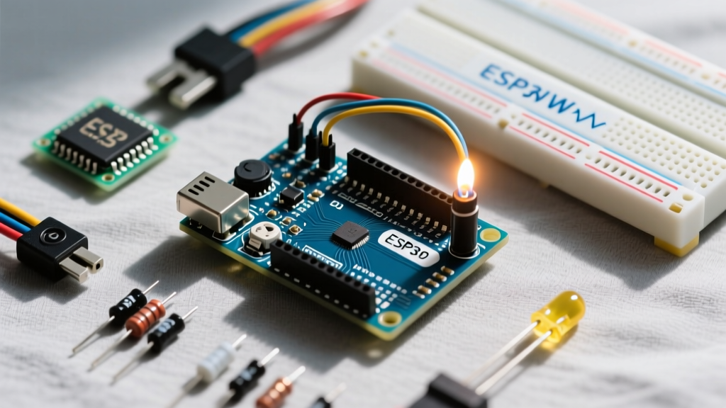
TimerOnelibrary to trigger step pulses via hardware interrupts, bypassing main-loop delays. - ESP32 MCPWM/RMT Peripherals: In 2026, most high-precision builds utilize the ESP32-S3. By routing step pulses through the ESP32's Remote Control (RMT) peripheral or MCPWM modules, pulse generation is offloaded to dedicated hardware silicon, achieving jitter-free step rates exceeding 200,000 steps per second.
Phase 4: Advanced TMC2209 UART Tuning
If you are using a modern Trinamic TMC2209 driver, relying solely on hardware pins leaves 80% of the chip's calibration potential untapped. Connecting the TMC2209's TX/RX pins to the Arduino's Serial1 (or SoftwareSerial) allows dynamic tuning of the motor's electromagnetic behavior.
Configuring StealthChop and CoolStep Thresholds
StealthChop2 provides silent operation but can struggle with rapid acceleration. CoolStep dynamically scales motor current based on load, reducing heat by up to 75%.
- TPWMTHRS (StealthChop Threshold): Set this to the velocity where your system transitions from fine positioning to rapid traverse. Below this threshold, the driver uses silent voltage PWM; above it, it switches to high-torque current-controlled SpreadCycle.
- SGTHRS (StallGuard Threshold): For sensorless homing, calibrate this value while the motor is running at a low, constant velocity. Decrease the value until the driver reliably triggers the DIAG pin upon physical impact with the limit switch.
Troubleshooting Calibration Failures
Even with perfect code, physical and electrical anomalies can ruin accuracy. Use this diagnostic matrix to isolate the root cause of your stepper driver Arduino issues.
| Symptom | Probable Root Cause | Calibration Fix |
|---|---|---|
| Motor stalls at high RPM | Inductive voltage spike limiting current decay | Increase VMOT voltage (up to 35V for DRV8825) to force faster coil current decay. |
| Positional drift over time | Accumulated missed steps due to low torque margin | Reduce acceleration ramp in AccelStepper; increase Vref by 10%. |
| Erratic speed / ringing noise | Arduino main-loop interrupt jitter | Move step pulse generation to a hardware timer or upgrade to ESP32. |
| Driver overheats and shuts down | Insufficient decay mode or poor heatsinking | Enable mixed-decay mode (if supported) or switch to TMC2209 with CoolStep. |
Final Thoughts on System Integration
Achieving true accuracy with a stepper driver Arduino setup requires treating the system as an integrated electromechanical loop. By meticulously setting your Vref reference voltages, respecting the physical torque limits of microstepping, and offloading pulse generation to hardware timers, you eliminate the variables that cause positional drift. For new builds in 2026, migrating to UART-enabled drivers like the TMC2209 paired with an ESP32 microcontroller provides the highest fidelity control available in the open-source hardware ecosystem.