
The Hall Effect Sensor Arduino Ecosystem: Choosing the Right Transducer
When integrating a hall effect sensor Arduino setup into your next electronics project, the sheer variety of available ICs can be paralyzing. Hall effect sensors transduce magnetic flux density into an electrical signal, but the way they process that signal varies wildly. A $0.15 digital switch behaves entirely differently from a $4.00 3-axis magnetometer, dictating your firmware complexity, wiring topology, and ultimate measurement precision.
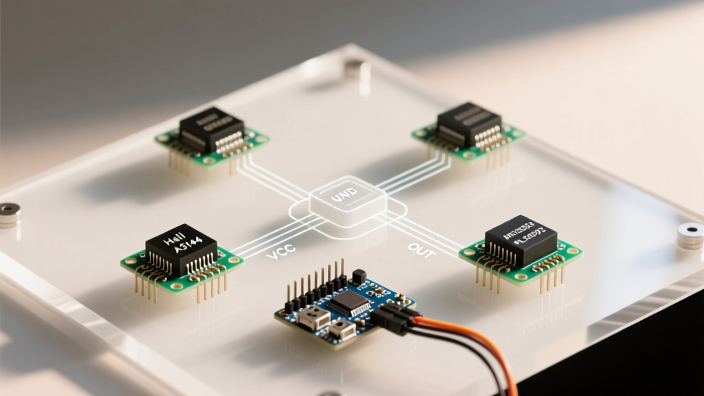
In this component comparison, we dissect the four most prevalent hall effect sensors used in microcontroller projects: the A3144 (digital unipolar), SS49E (analog linear), DRV5055 (precision analog), and MLX90393 (3-axis digital). We will evaluate their electrical characteristics, failure modes, and ideal use cases to help you select the exact component your application demands.
Quick Comparison Matrix
| Model | Sensor Type | Output Interface | Typical Price (2026) | Ideal Application |
|---|---|---|---|---|
| A3144 | Unipolar Switch | Digital (Open-Drain) | $0.10 - $0.25 | RPM counting, limit switches |
| SS49E | Linear | Analog (Ratiometric) | $0.50 - $0.90 | Proximity, basic current sensing |
| DRV5055 | Linear (Bipolar) | Analog (Ratiometric) | $1.20 - $1.80 | Precision joysticks, valve positioning |
| MLX90393 | 3-Axis Triaxis | I2C / SPI Digital | $3.50 - $5.00 | 3D spatial tracking, advanced knobs |
1. A3144: The Digital Unipolar Workhorse
The A3144 is the most ubiquitous hall effect sensor on the market. It is a unipolar switch, meaning it triggers only when exposed to a specific magnetic pole (usually the South pole) exceeding its operate point (BOP), and releases when the field drops below its release point (BRP).
Electrical Characteristics & Wiring
The A3144 features an open-collector (open-drain) output. This is a critical detail that trips up many beginners: the sensor cannot drive the signal line HIGH on its own. You must connect a 10kΩ pull-up resistor between the signal pin and your Arduino's VCC (3.3V or 5V). Without it, the pin will float, resulting in erratic digital reads.
- Operate Point (BOP): ~30 Gauss (varies by manufacturer bin)
- Release Point (BRP): ~15 Gauss
- Hysteresis: ~15 Gauss (prevents output chatter when hovering near the threshold)
Edge Cases & Failure Modes
While excellent for counting gear teeth or measuring fan RPM, the A3144 suffers from severe temperature drift. As ambient temperature rises toward 85°C, the magnetic sensitivity drops, requiring a stronger magnet to trigger the switch. Furthermore, cheap clone A3144s often fail to switch cleanly at frequencies above 10 kHz, making them unsuitable for high-speed motor encoder applications.
2. SS49E: The Analog Linear Standard
Unlike the binary A3144, the SS49E outputs a continuous analog voltage proportional to the magnetic flux density. It is ratiometric, meaning its quiescent output (when no magnet is present) is exactly half of the supply voltage (VCC/2).
ADC Mapping and Firmware
When wiring the SS49E to an Arduino Uno's 10-bit ADC (0-1023), a 5V supply yields a quiescent reading of ~512. The sensitivity is typically 1.4 mV/Gauss. To convert ADC readings to Gauss in your firmware, use the following formula:
Gauss = (ADC_Value - 512) / (1.4 * (5000 / 1023))
This allows you to measure both the strength and the polarity of the magnetic field (North vs. South).
Hardware Layout & Noise Mitigation
The SS49E is highly susceptible to electromagnetic interference (EMI) and power supply ripple. If you are using this sensor near DC motors or switching regulators, you must place a 100nF ceramic decoupling capacitor as close to the VCC and GND pins as physically possible. According to Texas Instruments' guidelines on Hall-effect sensing, failing to decouple linear sensors in noisy environments can introduce up to 50mV of peak-to-peak noise, entirely destroying low-field resolution.
3. DRV5055: High-Precision Bipolar Linear
If the SS49E is the standard, the Texas Instruments DRV5055 is the premium upgrade. It is a bipolar linear sensor designed for applications requiring high accuracy and low noise density.
Why Choose the DRV5055?
- Lower Noise Floor: The DRV5055 outputs significantly less high-frequency noise than the SS49E, reducing the need for heavy software low-pass filtering.
- Temperature Compensation: TI integrates advanced temperature compensation circuitry, ensuring the sensitivity remains stable across the -40°C to 125°C range.
- Multiple Sensitivity Bins: You can purchase specific variants (e.g., DRV5055A1 vs DRV5055A4) tailored to your exact magnetic gap requirements, ranging from ±21mT to ±169mT.
Use Case: This is the go-to sensor for building custom analog joysticks, throttle position sensors, and precision linear actuators where sub-millimeter positional accuracy is required.
4. MLX90393: 3-Axis Spatial Tracking
For applications requiring volumetric magnetic tracking, single-axis sensors fall short. The Melexis MLX90393 is a 3-axis magnetometer that communicates via I2C or SPI, providing 16-bit resolution across the X, Y, and Z axes.
Integration Complexities
Wiring the MLX90393 to an Arduino requires level-shifting if your microcontroller operates at 5V, as the MLX90393 is strictly a 3.3V device. Exposing its I2C lines to 5V logic will degrade the IC over time. Furthermore, reading 3-axis data requires configuring internal registers (gain, resolution, oversampling) via the library, adding firmware overhead compared to a simple analogRead().
Use Case: Contactless 3D knobs, magnetic stylus tracking, and advanced security mechanisms where the exact spatial orientation of a magnet must be verified.
Troubleshooting Matrix: Common Failure Modes
When your hall effect sensor Arduino circuit behaves erratically, consult this troubleshooting matrix before replacing components:
| Symptom | Probable Cause | Hardware / Firmware Fix |
|---|---|---|
| A3144 pin reads random HIGH/LOW | Missing pull-up resistor on open-drain output. | Add 10kΩ resistor between Signal and VCC. |
| SS49E ADC value fluctuates wildly | Power supply noise / EMI from nearby motors. | Add 100nF decoupling cap; use twisted pair wiring. |
| Sensor saturates at 1023 (5V ADC) | Magnet is too strong or placed too close. | Increase air gap; use a weaker neodymium grade (e.g., N35 instead of N52). |
| MLX90393 fails I2C scan | Logic level mismatch or incorrect I2C address pins. | Use 3.3V logic; verify A0/A1 pin states match hex address. |
Final Verdict: Which Sensor Should You Specify?
Selecting the right hall effect sensor Arduino component boils down to the nature of your magnetic data:
- Choose the A3144 if you only need to know if a magnet is present or if you are counting pulses for RPM. It is cheap, robust, and requires minimal code.
- Choose the SS49E for basic proximity detection or DIY current sensing where budget is a priority and minor noise can be filtered in software.
- Choose the DRV5055 for professional-grade analog position sensing, joysticks, and environments with high thermal variance.
- Choose the MLX90393 when your project demands 3D spatial awareness, multi-axis rotation tracking, and digital bus integration.
By matching the sensor's physical topology and output architecture to your specific mechanical constraints, you eliminate the need for software workarounds and ensure long-term reliability in your embedded designs.