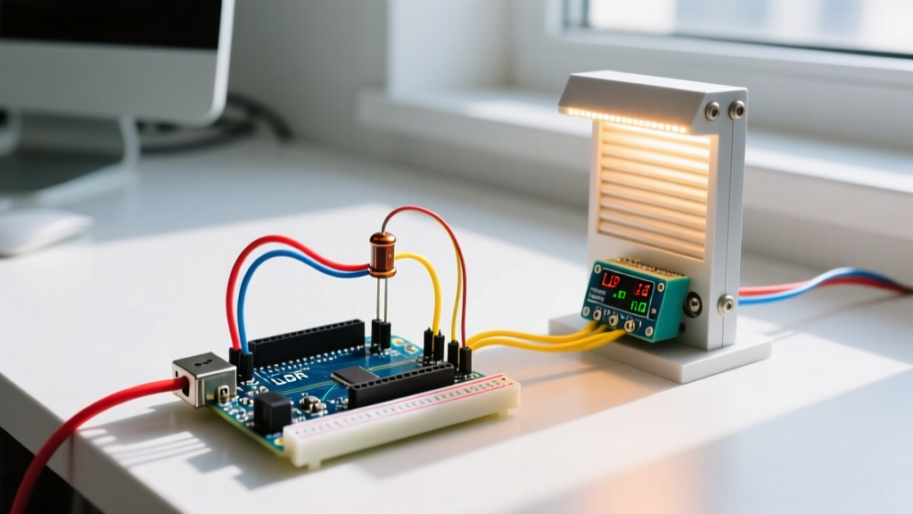

Beyond the Breadboard: Why Simple LDR Circuits Fail in the Field
Most introductory tutorials on using an LDR in Arduino projects stop at turning on an LED when the room gets dark. While this demonstrates basic analog-to-digital conversion, it completely ignores the harsh realities of real-world deployment. When you scale up to controlling high-current inductive loads—like a 12V linear actuator driving automated greenhouse shade screens—ambient light fluctuations, cloud cover transients, and relay chatter can quickly destroy your hardware.
In this guide, we will engineer a robust, field-ready automated shade controller. We will move past naive threshold checks and implement rolling average signal conditioning, software hysteresis (Schmitt trigger logic), and proper inductive kickback protection. By the end, you will have a commercial-grade light automation system ready for 2026 agricultural and smart-home deployments.
Bill of Materials (BOM) for a Heavy-Duty Shade Controller
To ensure reliability in humid, electrically noisy greenhouse environments, we are skipping the basic Arduino Uno and cheap 5V relay modules. Here is the professional-grade BOM with estimated 2026 pricing:
| Component | Model / Specification | Est. Cost (2026) | Purpose |
|---|---|---|---|
| Microcontroller | Arduino Nano Every (5V Logic) | $15.50 | Robust ATmega4809 core, better ADC stability than legacy Nano. |
| Light Sensor | GL5528 CdS Photoresistor | $0.65 | Peak spectral response at 540nm, ideal for sunlight tracking. |
| Pull-Down Resistor | 10kΩ 1% Metal Film | $0.10 | Forms the lower half of the voltage divider. |
| Relay Module | Omron G5V-2 (DPDT, 5V Coil) | $4.20 | High-reliability switching for motor polarity reversal. |
| Actuator | 12V 2-inch Stroke Linear Actuator | $48.00 | Provides the physical force to deploy/retract shade cloth. |
| Protection Diodes | 1N4007 Rectifier Diodes (x4) | $0.40 | Flyback protection for relay coils and the DC motor. |
Designing a Stable Voltage Divider for the GL5528
The Arduino Nano Every cannot read resistance directly; it measures voltage. To interface the LDR in Arduino, we must convert the changing resistance into a proportional voltage using a voltage divider circuit. According to SparkFun's guide on voltage dividers, the output voltage ($V_{out}$) is calculated as:
$V_{out} = V_{in} imes rac{R_{fixed}}{R_{LDR} + R_{fixed}}$
The GL5528 LDR has a dark resistance of approximately 1MΩ and a light resistance (at 10 Lux) of around 10kΩ to 20kΩ. If we use a standard 10kΩ fixed resistor to ground, the voltage at the analog pin will swing from nearly 0V in bright sunlight to roughly 4.95V in total darkness. This provides excellent resolution across the Arduino analogRead() 10-bit ADC range (0 to 1023).
Hardware Wiring Specifics
- Connect the 5V pin to one leg of the GL5528.
- Connect the other leg of the GL5528 to Analog Pin A0.
- Connect the 10kΩ resistor between A0 and GND.
- Place a 100nF ceramic capacitor in parallel with the 10kΩ resistor to form a hardware low-pass filter, attenuating high-frequency electrical noise from nearby greenhouse water pumps.
Signal Conditioning: Defeating Cloud Cover Transients
A naive script reads the analog pin and triggers the relay instantly. In an outdoor environment, a passing cloud can drop the light level below your threshold for 15 seconds, causing the actuator to partially close the shade, only to reverse direction when the sun reappears. This 'hunting' behavior will burn out your actuator motor within weeks.
To solve this, we implement a software rolling average (a digital low-pass filter). Instead of reacting to a single analogRead(), the Arduino maintains an array of the last 60 readings (sampled once per second). The actuator only responds to the 60-second moving average, effectively ignoring transient shadows from birds, clouds, or swaying branches.
The Dusk/Dawn Problem: Implementing Software Hysteresis
Even with a rolling average, you will face the dusk/dawn oscillation problem. As the sun sets, the ambient light level hovers right around your trigger threshold (e.g., an ADC value of 500). Minor atmospheric scattering will push the value to 498, triggering the 'close' relay. Seconds later, it drifts to 502, triggering the 'open' relay. This rapid relay chatter will weld the relay contacts shut and destroy the DPDT switching mechanism.
The engineering solution is software hysteresis, mimicking a Schmitt trigger. We establish two distinct thresholds: an Upper Bound and a Lower Bound, separated by a 'deadband'.
Hysteresis Logic Framework
- Deploy Shade (Dark): Trigger only when the 60-second average drops below 400 ADC.
- Retract Shade (Light): Trigger only when the 60-second average rises above 700 ADC.
- Deadband (401 - 699): Maintain the previous state. Do nothing.
This 300-unit deadband ensures that once the actuator moves, the light level must change drastically before a reversal command is issued. For a deeper understanding of the physics behind cadmium sulfide cells and their non-linear response curves, refer to the technical overview of photoresistors.
Protecting the Microcontroller from Inductive Kickback
When driving a 12V linear actuator, the motor acts as a massive inductor. When the relay cuts power, the collapsing magnetic field generates a high-voltage reverse spike (inductive kickback) that can easily exceed 100V. This spike will travel back through the relay module and fry the Arduino's 5V voltage regulator or the ATmega4809 GPIO pins.
Mandatory Protection Steps
- Relay Coil Protection: Solder a 1N4007 flyback diode in reverse bias directly across the 5V relay coil terminals (cathode to 5V, anode to the transistor collector).
- Motor Protection: Place a bidirectional TVS (Transient Voltage Suppression) diode or a 1N4007 diode across the actuator's power terminals. If using a DPDT relay for polarity reversal (to extend and retract the actuator), you must use a full-bridge rectifier configuration of four 1N4007 diodes to safely route the kickback spike back to the 12V power supply rails regardless of motor direction.
Field Calibration and Environmental Edge Cases
Deploying an LDR in Arduino setups outdoors requires physical protection. CdS photoresistors are highly sensitive to moisture and will drift wildly if condensation forms on the epoxy casing.
- Enclosure: Mount the GL5528 inside an IP65-rated polycarbonate enclosure with a clear UV-stabilized acrylic window. Do not use glass, as it blocks specific UV spectrums that might be relevant if you are also calculating DLI (Daily Light Integral) for plant growth.
- Conformal Coating: Apply an acrylic conformal coating (like MG Chemicals 419D) to the custom PCB holding the voltage divider and flyback diodes to prevent corrosion from high greenhouse humidity.
- Seasonal Calibration: Because the sun's angle changes drastically between summer and winter solstices, hardcoding ADC thresholds is a mistake. Implement a physical rotary potentiometer on an unused analog pin (e.g., A1) that acts as a manual baseline offset. This allows the greenhouse operator to tune the trigger point on the fly without needing a laptop to re-flash the Arduino firmware.
Summary
Using an LDR in Arduino projects for real-world automation requires much more than a basic if (light < 500) statement. By engineering a proper voltage divider, implementing a rolling average to filter cloud transients, applying software hysteresis to prevent relay chatter, and rigorously protecting against inductive kickback, you transform a fragile hobby circuit into a resilient, commercial-grade agricultural controller.