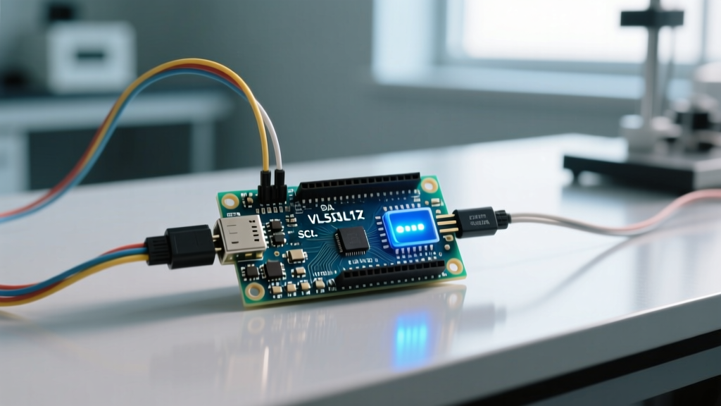

Beyond the HC-SR04: Why the Datasheet Matters
When makers search for how to create a distance sensor with arduino, 90% of tutorials default to the HC-SR04 ultrasonic module. While cheap ($2 to $3), ultrasonic sensors fail in acoustically noisy environments, struggle with sound-absorbing soft materials, and lack I2C addressability for multi-sensor arrays. In 2026, professional robotics and advanced DIY projects rely on Time-of-Flight (ToF) optics—specifically the STMicroelectronics VL53L1X.
This guide bypasses basic copy-paste library tutorials. We are going to decode the actual VL53L1X Datasheet to understand the silicon-level mechanics of ToF ranging. By reading the datasheet, you will learn how to configure Timing Budgets, manage the SPAD (Single Photon Avalanche Diode) array, and avoid the physical enclosure traps that blind poorly designed ToF sensors.
Silicon Showdown: Ultrasonic vs. ToF Optics
Before wiring up the Arduino, it is critical to understand the physical layer of the sensor you are integrating. The VL53L1X uses a Class 1, 940nm invisible infrared VCSEL (Vertical-Cavity Surface-Emitting Laser) to measure the time it takes for photons to bounce back to the receiver.
| Specification | HC-SR04 (Ultrasonic) | VL53L1X (ToF Optics) |
|---|---|---|
| Operating Principle | 40kHz Acoustic Echo | 940nm IR Photon Time-of-Flight |
| Max Range | ~400 cm | ~400 cm (Long Distance Mode) |
| Min Range (Blind Spot) | ~2 cm | ~4 cm |
| Interface | Trigger/Echo PWM | I2C (Addressable) |
| Field of View (FoV) | ~15° (Acoustic Cone) | Configurable (15° to 27° via ROI) |
| Avg. Module Cost (2026) | $2.50 | $12.00 - $16.00 |
Translating Datasheet Pinouts to Arduino I2C
If you are using a bare VL53L1X IC, the datasheet dictates strict 3.3V logic and power limits. However, most Arduino users will use a carrier board, such as the Pololu #3415 VL53L1X Carrier, which includes an onboard LDO and level shifters, allowing safe 5V Arduino Uno/Mega integration.
The XSHUT Pin: The Key to Multi-Sensor Arrays
Section 4.1 of the datasheet details the XSHUT (Shutdown) pin. This is an active-low hardware reset. Out of the factory, every VL53L1X shares the default I2C address of 0x29. If you connect two sensors to the same I2C bus, they will collide and crash the bus.
The Datasheet Solution: To use multiple sensors, wire the XSHUT pin of each sensor to a separate Arduino digital GPIO. Pull all XSHUT pins LOW to put them in hardware standby. Then, pull one XSHUT HIGH, wait 1.2ms (the datasheet's specified boot time), use the Arduino Wire Library to change its I2C address in RAM, and repeat for the next sensor.
Datasheet Warning: The XSHUT pin is not internally pulled up on the bare silicon. If left floating, ambient EMI can cause the sensor to randomly reboot during operation. Always ensure your carrier board has a pull-up resistor, or add a 10kΩ external pull-up to VCC.
Timing Budgets and Distance Modes (The Core Logic)
The most misunderstood aspect of the VL53L1X is the relationship between Distance Mode and Timing Budget. The datasheet defines four preset distance modes that alter the VCSEL pulse width and the SPAD array sensitivity.
- Short Mode: Optimized for high ambient light rejection. Max range ~1.3m. Best for indoor line-following robots.
- Medium Mode: Balanced. Max range ~3m.
- Long Mode: Maximum VCSEL power. Max range ~4m. Requires dark environments or highly reflective targets to achieve max range.
The Timing Budget Trap
The Timing Budget is the exact amount of time the sensor spends integrating returning photons. The datasheet strictly couples the Timing Budget to the Distance Mode. If you attempt to set a 20ms Timing Budget while in 'Long Mode', the sensor will return a Range Status Error (usually Status 7: 'Min range limit exceeded' or Status 2: 'Signal fail').
| Distance Mode | Minimum Timing Budget | Recommended Budget | Max Update Rate |
|---|---|---|---|
| Short | 20 ms | 33 ms | ~30 Hz |
| Medium | 33 ms | 50 ms | ~20 Hz |
| Long | 100 ms | 200 ms | ~5 Hz |
Actionable Advice: For a standard Arduino obstacle-avoidance rover moving at 1 meter per second, configure the sensor to Medium Mode with a 50ms Timing Budget. This provides a reliable 2-meter detection range with a 20Hz refresh rate, ensuring the Arduino has enough processing time to brake the motors between readings.
Region of Interest (ROI): Shaping the Laser Beam
Unlike ultrasonic sensors that emit a fixed acoustic cone, the VL53L1X features a 16x16 SPAD array (256 individual photon detectors). The datasheet allows you to define a Region of Interest (ROI), effectively masking off the outer pixels to narrow the Field of View (FoV).
By default, the ROI is set to the maximum 16x16 grid, yielding a ~27° FoV. If your Arduino project involves navigating through narrow doorways or detecting thin objects like chair legs, a wide FoV will cause false positives from adjacent walls. By reducing the ROI to a 4x4 grid in the center of the array via I2C register writes, you narrow the FoV to ~15°, drastically reducing peripheral phantom echoes.
Real-World Failure Mode: Cover Glass Crosstalk
The most common reason a VL53L1X fails in a finished product is physical enclosure design. Section 6.2 of the STMicroelectronics datasheet explicitly warns about Cover Glass Crosstalk.
When you mount the sensor behind a protective acrylic or polycarbonate window on your robot chassis, the 940nm VCSEL laser hits the inner surface of the window. A portion of this light reflects internally and travels directly into the SPAD receiver, bypassing the outside world entirely. The sensor interprets this immediate reflection as an object located at 0cm, permanently blinding the sensor.
Engineering the Solution
- The Air Gap: The datasheet mandates a minimum air gap of 100µm between the sensor's built-in cover glass and your external enclosure window. Never mount the sensor flush against the inside of an acrylic panel.
- Optical Shrouds: 3D print a TPU or matte-black PLA shroud that physically separates the TX (transmit) and RX (receive) sides of the sensor aperture, preventing internal chassis reflections.
- Software Calibration: If a window is unavoidable, the datasheet outlines a 'Crosstalk Calibration' routine. This involves pointing the sensor at a target at a known distance, measuring the internal reflection offset, and writing a compensation value to the sensor's crosstalk compensation registers before starting the ranging state machine.
Implementing the Datasheet State Machine in Arduino
While the Pololu_VL53L1X library abstracts the I2C hex codes, understanding the underlying state machine from the datasheet is vital for debugging. A proper initialization sequence must follow this exact order:
- Boot & Wait: Pull XSHUT high, wait for GPIO1 to go high (indicating the firmware has booted from ROM to RAM).
- Load Tuning Parameters: Write the 400+ bytes of default tuning parameters (provided in the ST API source code) to the sensor's RAM.
- Set Distance Mode & Timing Budget: Write to the specific configuration registers to define the operational envelope.
- Start Ranging: Trigger the continuous measurement loop.
- Interrupt Polling: Monitor the GPIO1 pin. The datasheet specifies that GPIO1 pulls LOW when a new range measurement is ready in the output buffer, saving the Arduino from blindly polling the I2C bus and wasting clock cycles.
Summary: Designing with Intent
Learning how to create a distance sensor with arduino using the VL53L1X is not just about wiring four pins and calling sensor.read(). It requires respecting the physics of 940nm light, adhering to the strict timing budgets outlined in the silicon datasheet, and designing mechanical enclosures that prevent optical crosstalk. By treating the datasheet as your primary blueprint rather than an afterthought, you elevate your Arduino projects from fragile prototypes to robust, production-ready systems.