
Why the DS18B20 Dominates Precision Temperature Logging
When building environmental monitors, 3D printer enclosures, or liquid cooling telemetry systems, the arduino temp sensor ds18b20 remains the undisputed industry standard for hobbyists and embedded engineers alike. Originally designed by Dallas Semiconductor, later acquired by Maxim Integrated, and now maintained by Analog Devices, the DS18B20 offers a fully digital, calibrated output that eliminates the analog-to-digital conversion drift inherent in thermistors or the LM35.
Unlike the DHT11 or DHT22, which measure ambient air temperature and humidity with sluggish response times, the DS18B20 utilizes a direct-to-digital 1-Wire interface. This allows multiple sensors to share a single digital pin on your microcontroller, each identified by a factory-lasered 64-bit unique ROM address. In this comprehensive integration tutorial, we will cover advanced wiring topologies, non-blocking code architectures, and critical hardware authentication to ensure your 2026 data logging projects are bulletproof.
Technical Specifications and Hardware Variants
Before writing a single line of C++, it is vital to understand the electrical boundaries of the silicon. The DS18B20 operates across a wide voltage envelope and provides user-configurable resolution.
| Parameter | Specification | Engineering Notes |
|---|---|---|
| Supply Voltage (VDD) | 3.0V to 5.5V | Ideal for both 5V Arduino Uno and 3.3V ESP32/RP2040 logic levels. |
| Accuracy | ±0.5°C (from -10°C to +85°C) | Accuracy degrades to ±1.0°C at extreme ranges (-55°C to +125°C). |
| Resolution | 9-bit to 12-bit (Configurable) | 12-bit yields 0.0625°C increments but requires longest conversion time. |
| Interface | 1-Wire (Requires 4.7kΩ Pull-up) | Bus capacitance limits cable length; active pull-ups needed for >10m. |
Form Factors: TO-92 vs. Waterproof Probes
The bare TO-92 transistor package is excellent for PCB mounting and rapid ambient air sensing. However, for hydroponics, brewing, or outdoor weather stations, the waterproof stainless steel probe variant is mandatory. These probes encapsulate the silicon in a 304 stainless steel tube (typically 6mm x 30mm) sealed with thermal epoxy, connected via a 1-meter PVC-jacketed cable. While robust, this metal housing introduces significant thermal mass, which we will address in the deployment strategies below.
The Counterfeit Silicon Epidemic: Sourcing Genuine Parts
2026 Supply Chain Warning: The market is currently flooded with cloned DS18B20 chips selling for $0.50 to $0.80 on bulk marketplaces. These clones often fail the strict microsecond timing slots required by the 1-Wire protocol, resulting in random CRC (Cyclic Redundancy Check) errors, phantom devices on the bus, or complete failure when multiple sensors are chained together. Always source genuine Analog Devices silicon from authorized distributors like Mouser or DigiKey, where authentic units typically range from $2.50 to $3.20 per unit.
You can verify authenticity in software by checking the ROM address family code. Genuine chips will reliably return 0x28 as the first byte of their 64-bit address and pass the strict CRC-8 validation implemented in the official OneWire library. For deeper hardware validation, refer to the Analog Devices DS18B20 official product documentation, which details the specific scratchpad memory behaviors that clones frequently emulate incorrectly.
1-Wire Wiring Topologies: Standard vs. Parasite Power
The 1-Wire protocol is a marvel of minimalism, but it demands precise electrical termination. The data line is an open-drain bus, meaning the sensor can only pull the line LOW. To return the line HIGH, a pull-up resistor is mandatory.
Standard External Power Mode (Recommended)
- Pin 1 (GND): Connect to Arduino GND.
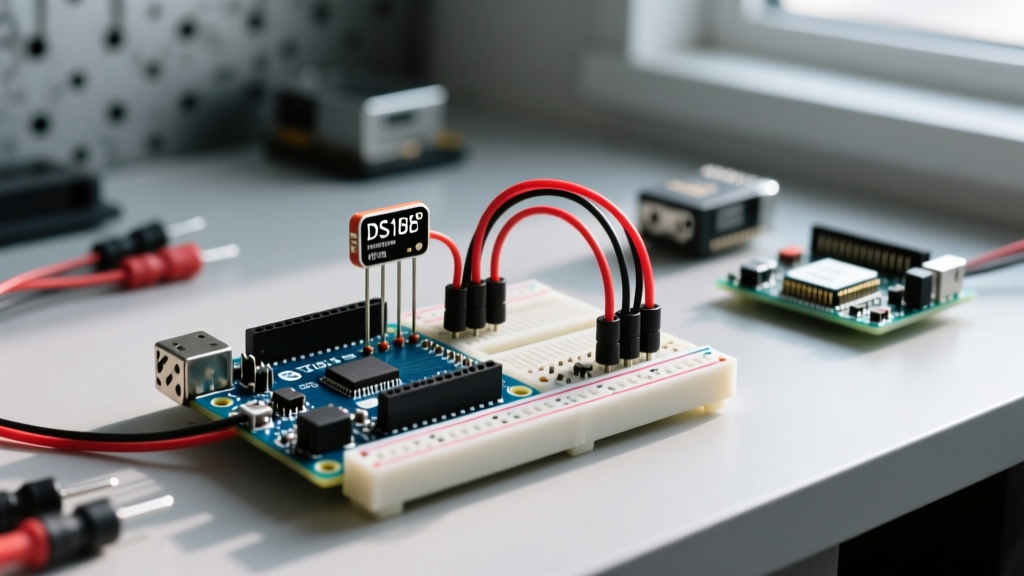
- Pin 2 (Data): Connect to your chosen digital pin (e.g., Pin 2). Place a 4.7kΩ resistor between this Data line and the 5V/VDD line.
- Pin 3 (VDD): Connect to Arduino 5V (or 3.3V for ESP32).
Expert Tip: If your cable run exceeds 15 meters, the parasitic capacitance of the copper wire will slow the voltage rise time, corrupting data. In these edge cases, drop the pull-up resistor to 2.2kΩ or implement an active MOSFET-based pull-up circuit.
Parasite Power Mode
In parasite mode, the DS18B20 siphons power directly from the data line during conversions, storing it in an internal capacitor. To wire this, tie both Pin 1 and Pin 3 to GND, leaving only Pin 2 connected to the microcontroller (with the 4.7kΩ pull-up to VDD). While this saves a wire, it severely limits bus length and can cause brownouts during the 12-bit temperature conversion phase, which draws up to 1.5mA. We strongly advise against parasite mode for multi-drop networks.
Step-by-Step Arduino Integration and Async Code
To interface with the sensor, you will need two foundational libraries: the PJRC OneWire Library for the low-level protocol timing, and the DallasTemperature Control Library for high-level scratchpad parsing.
The Blocking Code Trap
Most beginner tutorials use the sensors.requestTemperatures() function synchronously. By default, this command halts the microcontroller for up to 750 milliseconds while the sensor performs the analog-to-digital conversion. In a real-time system controlling PID loops or reading high-frequency interrupts, a 750ms blocking delay is catastrophic.
Implementing Non-Blocking Asynchronous Reads
To achieve professional-grade firmware architecture, you must decouple the conversion request from the data retrieval. Here is the structural logic for a non-blocking implementation:
- Initialize the library and immediately call
sensors.setWaitForConversion(false); - Trigger the conversion manually using
sensors.requestTemperatures(); - Record the current time using
unsigned long conversionStart = millis(); - Allow the main
loop()to continue executing other tasks (e.g., updating displays, handling network traffic). - Use a conditional check:
if (millis() - conversionStart >= 750)to determine when the ADC process is complete. - Once the time has elapsed, call
sensors.getTempCByIndex(0);to fetch the value from the sensor's scratchpad memory without delaying the CPU.
Optimizing Resolution and Conversion Timings
The DS18B20 ships with 12-bit resolution enabled by default. However, you can dynamically adjust this via software to trade precision for speed. This is configured by writing to the sensor's Configuration Register (0x04).
| Resolution (Bits) | Temperature Increment | Max Conversion Time | Best Use Case |
|---|---|---|---|
| 9-bit | 0.5°C | 93.75 ms | Rapid thermal fault detection, basic HVAC limits. |
| 10-bit | 0.25°C | 187.5 ms | General room ambient monitoring. |
| 11-bit | 0.125°C | 375 ms | Server rack inlet temperature tracking. |
| 12-bit | 0.0625°C | 750 ms | Laboratory calorimetry, precision liquid baths. |
Code Implementation: Use sensors.setResolution(10); during your setup() routine to drop the resolution to 10-bit, effectively cutting your asynchronous wait time by 75%.
Real-World Troubleshooting: Edge Cases and Failure Modes
Even with perfect wiring, environmental factors and bus contention can cause anomalous readings. Here is how to diagnose the most common field failures:
- The "-127°C" Error: This is the DallasTemperature library's default error code when a device is not found or the CRC check fails. 90% of the time, this indicates a missing or improperly seated 4.7kΩ pull-up resistor, or a shared ground fault where the sensor ground is not referenced to the Arduino ground.
- The "85°C" Power-On Default: If your sensor consistently reads exactly 85.0°C upon boot, you are reading the scratchpad before the first conversion has completed. The power-on reset value of the temperature register is 85°C. Ensure your code waits for the initial 750ms conversion window before polling the data.
- Thermal Mass Lag in Waterproof Probes: If you are using a stainless steel probe to measure ambient air temperature, you will notice a severe lag (sometimes taking 3 to 5 minutes to stabilize). The metal tube and internal epoxy act as a heat sink. For rapid air sensing, strip the PVC jacket and use a bare TO-92 sensor suspended in a 3D-printed radiation shield. If you must use the metal probe in liquids, stir the liquid or apply a thin layer of thermal paste between the probe and the heat source to minimize the boundary layer resistance.
- Ghost Devices on the Bus: If
sensors.getDeviceCount()returns more devices than you physically connected, you are experiencing signal reflection on long, unterminated wire branches. Avoid "star" wiring topologies; always route your 1-Wire bus in a daisy-chain (linear) configuration to maintain signal integrity.
Conclusion
Mastering the arduino temp sensor ds18b20 requires moving beyond basic copy-paste tutorials. By understanding the underlying 1-Wire timing constraints, implementing non-blocking asynchronous code, and respecting the physical realities of thermal mass and bus capacitance, you can build industrial-grade telemetry systems on a hobbyist budget. Always verify your hardware sources, utilize the correct pull-up topologies, and leverage the sensor's configurable resolution to perfectly match your project's specific data acquisition requirements.