
Why Use a Sensor Shield for OLED Integration?
Breadboard spaghetti is the enemy of reliable sensor nodes. When integrating environmental sensors with a visual output, learning how to connect OLED to Arduino Sensor Shield hardware streamlines your prototyping phase into a robust, semi-permanent assembly. The Arduino Sensor Shield V5.0 eliminates the need for messy soldering or unreliable jumper wires by providing dedicated, clearly labeled I2C headers. This is particularly critical when chaining multiple peripherals, as I2C bus capacitance and signal integrity degrade rapidly on unshielded breadboards.
In this 2026 integration tutorial, we will bypass generic wiring diagrams and focus on the electrical realities of pairing a standard SSD1306 0.96-inch OLED with the Sensor Shield V5.0. We will cover logic-level translation, pull-up resistor collisions, and the notorious counterfeit controller trap that plagues modern DIY electronics.
2026 Hardware Bill of Materials (BOM)
Before wiring, verify your specific hardware revisions. The market is flooded with clones that deviate from standard pinouts. The following components represent the most reliable baseline for this tutorial:
| Component | Specific Model / Revision | Est. 2026 Price | Key Specification |
|---|---|---|---|
| Microcontroller | Arduino Uno R4 Minima | $27.50 | 5V Logic, 48MHz Cortex-M4 |
| Expansion Board | Sensor Shield V5.0 (Deek Robot / Generic) | $4.50 - $6.00 | Dedicated I2C header, APC220 RF interface |
| Display | 0.96" 128x64 I2C OLED (SSD1306) | $4.00 - $7.00 | 4-pin I2C, 3.3V LDO onboard |
| Wiring | Female-to-Female Dupont (20cm) | $3.00 (pack) | 24 AWG silicone stranded |
Wiring Matrix: OLED to Sensor Shield V5.0
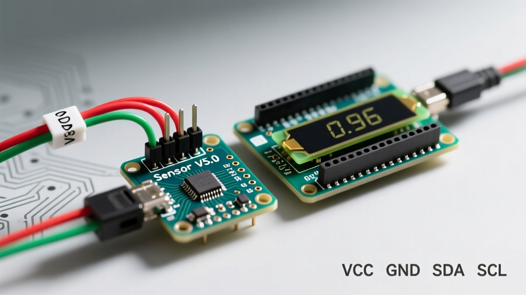
The Sensor Shield V5.0 features a dedicated I2C interface block, usually located near the analog pin headers. This block is hardwired to the ATmega328P's A4 (SDA) and A5 (SCL) pins. Do not connect the OLED to the standard analog pin rows; use the dedicated I2C header to maintain signal integrity and physical stability.
Pinout Mapping Table
| OLED Pin (SSD1306) | Sensor Shield V5.0 Header | Function & Notes |
|---|---|---|
| GND | I2C Header: GND | Common ground reference. Essential for stable I2C. |
| VCC | I2C Header: VCC (5V) | Powers the onboard 3.3V LDO regulator. |
| SCL | I2C Header: SCL | Serial Clock. Routes to Uno Pin A5. |
| SDA | I2C Header: SDA | Serial Data. Routes to Uno Pin A4. |
Expert Warning: Some older V4.0 sensor shields label the I2C pins as 'A4' and 'A5' directly on the analog rail. The V5.0 separates them into a 4-pin block. Always trace the PCB silkscreen to confirm you are using the dedicated I2C block.
The 5V vs 3.3V Logic Level Trap
The most common failure mode when connecting an OLED to an Arduino Sensor Shield is ignoring logic level thresholds. The Arduino Uno R3 and R4 operate at 5V logic. The SSD1306 controller is natively a 3.3V device. While most commercial OLED breakout boards include a 3.3V LDO (Low Dropout Regulator) to handle the 5V VCC input, they rarely include logic level shifters for the SDA and SCL lines.
Why It Matters in 2026
Feeding 5V logic into the 3.3V SDA/SCL pins of the SSD1306 violates the absolute maximum ratings of the silicon. While many hobbyists report 'it just works' due to the open-drain nature of the I2C bus, prolonged exposure degrades the input protection diodes, leading to ghosting, dead pixels, or total controller failure. According to the Arduino Wire Library Documentation, the I2C bus relies on external pull-up resistors. If your sensor shield pulls the lines up to 5V, the OLED is subjected to 5V on its data pins.
The Professional Solution
If you are building a node for long-term deployment, insert a bi-directional logic level converter (like the BSS138-based SparkFun BOB-12009) between the Sensor Shield's I2C header and the OLED. For rapid prototyping, relying on the OLED's internal clamping diodes is common practice, but you accept the risk of reduced lifespan.
Firmware: Initializing the SSD1306
To drive the display, we utilize the industry-standard Adafruit libraries. Ensure you have installed both Adafruit_SSD1306 and Adafruit_GFX via the Arduino Library Manager. For a comprehensive overview of the display's memory buffer architecture, refer to the Adafruit Monochrome OLED Breakouts Guide.
#include <Wire.h>
#include <Adafruit_SSD1306.h>

#define SCREEN_WIDTH 128
#define SCREEN_HEIGHT 64
#define OLED_RESET -1
#define SCREEN_ADDRESS 0x3C // Verify with I2C Scanner

Adafruit_SSD1306 display(SCREEN_WIDTH, SCREEN_HEIGHT, &Wire, OLED_RESET);

void setup() {
  Serial.begin(115200);

  // Initialize the I2C bus and OLED
  if(!display.begin(SSD1306_SWITCHCAPVCC, SCREEN_ADDRESS)) {
    Serial.println(F("SSD1306 allocation failed"));
    for(;;); // Halt execution on failure
  }

  display.clearDisplay();
  display.setTextSize(1);
  display.setTextColor(SSD1306_WHITE);
  display.setCursor(0, 10);
  display.print("ElectricalFlux");
  display.setCursor(0, 25);
  display.print("Sensor Shield I2C OK");
  display.display();
}

void loop() {
  // Sensor polling logic goes here
}
Multi-Sensor Integration on the Same Bus
The true advantage of the Sensor Shield V5.0 is the ability to daisy-chain sensors. Let's say you want to add a BME280 temperature/humidity sensor alongside your OLED. Both devices will connect to the same SDA/SCL headers (you can use a breadboard or an I2C multiplexer like the TCA9548A if headers are limited).
The Pull-Up Resistor Collision
I2C requires pull-up resistors on the SDA and SCL lines. The Sensor Shield V5.0 typically does not include onboard pull-ups, relying on the Arduino's internal weak pull-ups or the modules themselves. However, both the BME280 breakout and the SSD1306 OLED usually feature 4.7kΩ pull-up resistors to 3.3V.
- Parallel Resistance: Two 4.7kΩ resistors in parallel yield ~2.35kΩ.
- The Problem: A 2.35kΩ pull-up to 3.3V draws roughly 1.4mA when the line is pulled low. This is within the ATmega328P's 3mA sink limit, but if you add a third sensor, the resistance drops further, potentially causing voltage droop and I2C ACK failures.
- The Fix: If the bus becomes unstable, physically remove the SMD pull-up resistors from one of the sensor modules using a hot air rework station, or use an active I2C bus accelerator like the PCA9600.
Advanced Troubleshooting: Edge Cases & Failures
When your OLED remains black after uploading the code, do not immediately assume the display is dead. Run through this diagnostic matrix:
1. The I2C Address Mismatch
While 90% of 0.96" OLEDs use the I2C address 0x3C, some manufacturers wire the SA0 pin high, shifting the address to 0x3D. Always run an I2C Scanner sketch before hardcoding the address. The Adafruit I2C Address List is an invaluable bookmark for verifying default peripheral addresses.
2. The Counterfeit SH1106G Trap
Due to global supply chain quirks, many displays labeled as 'SSD1306' on the silkscreen actually house the SH1106G controller. The SH1106G has a slightly larger internal RAM buffer (132x64 instead of 128x64). If your code compiles but the display shows shifted columns or vertical tearing, change your library initialization to use the Adafruit_SH110X library instead of the SSD1306 variant.
3. Capacitance and Wire Length
The I2C specification limits bus capacitance to 400pF. Female-to-female Dupont wires add roughly 15-20pF per 10cm. If you are routing the OLED to the front panel of an enclosure using 30cm wires, the added capacitance will round off the sharp edges of the I2C clock signal, causing data corruption. Keep I2C traces under 20cm, or reduce the I2C clock speed from the default 100kHz to 50kHz using Wire.setClock(50000); in your setup function.
Summary
Connecting an OLED to an Arduino Sensor Shield is a foundational skill for building standalone diagnostic tools and environmental monitors. By respecting the 5V/3.3V logic boundaries, managing I2C pull-up resistor networks, and verifying controller silicon, you transition from fragile breadboard prototypes to robust, field-ready sensor arrays. The Sensor Shield V5.0 remains an indispensable, low-cost bridge between microcontroller logic and real-world peripheral integration.