
Mastering Proportional Sensor Feedback with the ATmega328P
Integrating environmental sensors with active cooling or heating elements is a cornerstone of embedded systems design. While reading a temperature or humidity sensor is straightforward, executing a smooth, closed-loop proportional response requires a deep understanding of Pulse Width Modulation (PWM). In 2026, despite the proliferation of 32-bit ARM Cortex microcontrollers, the classic Arduino Nano (based on the Microchip ATmega328P) remains an industry workhorse for industrial sensor nodes and DIY thermal management systems due to its robust 5V logic and predictable timer architecture.
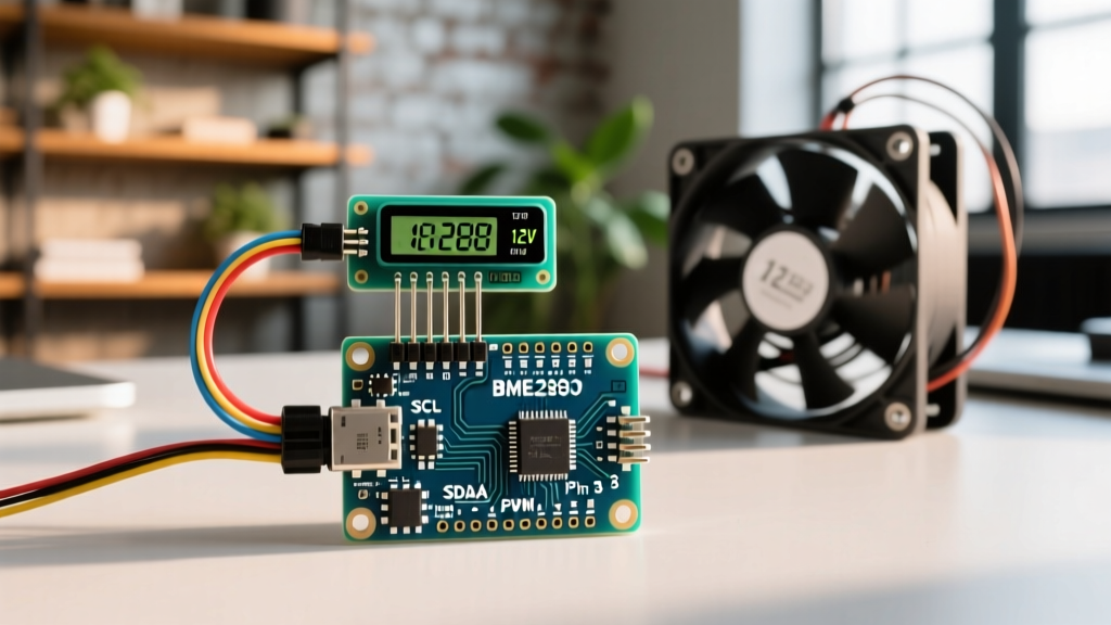
This tutorial moves beyond basic LED fading. We will explore the specific hardware timers tied to the arduino pwm pins nano and build a closed-loop thermal management system. By mapping real-time data from a Bosch BME280 environmental sensor to a 12V PWM-controlled cooling fan via a logic-level MOSFET, you will learn how to implement proportional control while avoiding the common hardware pitfalls that destroy microcontrollers and power stages.
Anatomy of Arduino PWM Pins Nano: Timers and Frequencies
The Arduino Nano features six hardware PWM-capable pins, marked with a tilde (~) on the silkscreen: D3, D5, D6, D9, D10, and D11. However, not all PWM pins are created equal. They are driven by three distinct internal hardware timers, which dictate their default switching frequencies and side effects.
| PWM Pin | Hardware Timer | Default Frequency | Critical System Notes |
|---|---|---|---|
| D3 | Timer 2 (8-bit) | ~490 Hz | Safe for motor/fan control. |
| D5 | Timer 0 (8-bit) | ~980 Hz | Warning: Timer 0 handles millis() and delay(). Altering its prescaler breaks timekeeping. |
| D6 | Timer 0 (8-bit) | ~980 Hz | Warning: Same as D5. Avoid for frequency-sensitive analog filtering. |
| D9 | Timer 1 (16-bit) | ~490 Hz | Ideal for high-resolution control and frequency modification. |
| D10 | Timer 1 (16-bit) | ~490 Hz | Shares Timer 1 with D9. |
| D11 | Timer 2 (8-bit) | ~490 Hz | Shares Timer 2 with D3. |
According to the Microchip ATmega328P Datasheet, Timer 1 is a 16-bit timer, offering finer resolution for duty cycle adjustments compared to the 8-bit Timers 0 and 2. For sensor-driven proportional control, Pin D9 is our optimal choice, as it allows for high-resolution mapping without risking the core timing functions of the Arduino framework.
Project BOM: Engineering a 12V Proportional Fan Circuit
To build a robust closed-loop system, we must interface the Nano's 5V logic with a 12V power stage. A frequent mistake in beginner tutorials is the use of an IRF520 MOSFET. The IRF520 requires a Gate-Source Voltage ($V_{GS}$) of 10V to fully turn on; driving it with 5V from the Nano leaves it in the linear (ohmic) region, causing it to overheat and fail rapidly.
2026 Component Selection & Pricing
- Microcontroller: Arduino Nano (Official or reputable clone with CH340/FTDI). ($6.00 - $24.00)
- Sensor: Bosch BME280 Breakout (I2C). Measures temperature, humidity, and pressure. ($4.00 generic / $15.00 Adafruit 2652)
- Power Switch: IRLB8721PBF Logic-Level N-Channel MOSFET. Fully saturated at $V_{GS}$ = 4.5V. ($1.50)
- Actuator: 12V DC Brushless Cooling Fan (2-wire or 4-wire). ($8.00)
- Passives: 100Ω gate resistor, 10kΩ gate pull-down resistor, 1N4007 flyback diode. ($1.00 total)
Wiring the Sensor and PWM Power Stage
Proper wiring is critical to prevent inductive kickback from destroying the Nano's PWM pin and to ensure clean I2C communication.
1. BME280 I2C Sensor Integration
The BME280 communicates via I2C. Connect the breakout board as follows:
- VIN: Nano 5V (or 3.3V depending on breakout regulator)
- GND: Nano GND
- SCL: Nano A5
- SDA: Nano A4
Expert Note: If using a generic bare-bones BME280 module without onboard pull-ups, you must add 4.7kΩ pull-up resistors to the SDA and SCL lines to prevent I2C bus lockups in electrically noisy environments.
2. The PWM MOSFET Driver Circuit
We will use Pin D9 to drive the gate of the IRLB8721PBF MOSFET.
- Connect Nano D9 to the MOSFET Gate through a 100Ω resistor (limits inrush current to the gate capacitance, protecting the ATmega328P IO pin).
- Connect a 10kΩ resistor between the MOSFET Gate and GND. This pull-down ensures the fan stays off during Nano boot-up when pins are floating.
- Connect the MOSFET Source to the 12V Power Supply GND and the Nano GND (Common Ground is mandatory).
- Connect the Fan's negative wire to the MOSFET Drain.
- Connect the Fan's positive wire to the 12V Power Supply (+12V).
- Place a 1N4007 flyback diode in reverse bias across the fan terminals (Cathode to +12V, Anode to Drain) to clamp inductive voltage spikes when the PWM signal switches off.
Proportional Control Logic and Code Strategy
Instead of a simple on/off threshold (bang-bang control), we use a proportional mapping algorithm. We define a minimum temperature threshold where the fan begins to spin, and a maximum threshold where it runs at 100% duty cycle.
Acoustic Coil Whine Mitigation: The default 490 Hz PWM frequency on Pin D9 often causes an audible, irritating whine in DC fan motors. Because D9 uses the 16-bit Timer 1, we can modify the timer prescaler in the setup() function to push the PWM frequency to ~31 kHz, moving it above human hearing. Refer to the Arduino PWM Documentation for advanced timer register manipulation.
Implementation Snippet: Timer Modification & Mapping
Below is the core logic for adjusting Timer 1 and mapping the sensor data to the PWM output.
// Shift Timer 1 to ~31kHz PWM to eliminate acoustic motor noise
TCCR1B = (TCCR1B & 0b11111000) | 0x01;

// Read sensor (using Adafruit BME280 library)
float currentTemp = bme.readTemperature();

// Define control band
const float TEMP_MIN = 28.0; // Fan starts at 28C
const float TEMP_MAX = 45.0; // Fan at 100% at 45C

int pwmValue = 0;
if (currentTemp >= TEMP_MAX) {
  pwmValue = 255;
} else if (currentTemp > TEMP_MIN) {
  // Map temperature to 8-bit PWM resolution
  pwmValue = map(currentTemp * 100, TEMP_MIN * 100, TEMP_MAX * 100, 75, 255);
  // 75 is the minimum PWM value required to overcome fan stiction
}

analogWrite(9, pwmValue);
Real-World Failure Modes & Troubleshooting
When deploying this circuit in the field, theoretical code often meets physical reality. Here are the most common edge cases and how to resolve them:
- Fan Stalling at Low PWM: Brushless DC fans require a minimum voltage to overcome static friction (stiction). If your
map()function outputs a PWM value below 30-40 (approx. 12%), the fan may stall and hum. Always map your minimum proportional output to at least 75 (approx. 30% duty cycle) to guarantee rotation. - Nano Resetting Randomly: If you omitted the 1N4007 flyback diode, the inductive collapse of the fan's magnetic field generates high-voltage spikes that couple back into the Nano's ground plane, triggering the ATmega328P's brown-out detection (BOD) reset. Always use the diode.
- I2C Sensor Freezing: The BME280 may lock up if the 12V fan wiring is routed too closely to the I2C SDA/SCL lines, inducing electromagnetic interference (EMI). Keep high-current PWM paths physically separated from low-voltage sensor traces, and ensure twisted-pair wiring for I2C runs exceeding 15cm.
- Non-Linear Thermal Response: Airflow does not scale linearly with PWM duty cycle; it follows a cubic relationship regarding power. For highly precise laboratory thermal chambers, replace the simple
map()function with a PID (Proportional-Integral-Derivative) control library to eliminate steady-state error and temperature overshoot.
By respecting the hardware timers of the arduino pwm pins nano and engineering a proper logic-level power stage, you transform a basic microcontroller into a highly reliable, closed-loop environmental controller capable of handling demanding industrial and DIY thermal loads.