
The Hidden Cost of Uncalibrated Stepper Motors
In the realm of DIY CNC routing, 3D printing, and automated lab equipment, stepper motors are the undisputed workhorses of linear and rotational motion. However, a common pitfall among makers and junior engineers is treating stepper motors as inherently perfect open-loop systems. They are not. Without precise calibration, the theoretical Arduino code for stepper motor control will inevitably diverge from physical reality, resulting in dimensional inaccuracies, layer shifting, and accumulated positional drift.
Calibration is not merely about setting the correct steps-per-millimeter; it is about harmonizing the electrical current, microstepping interpolation, mechanical load, and acceleration curves. This guide provides a rigorous, metrology-focused approach to calibrating your stepper systems, complete with optimized code and hardware selection strategies relevant to the 2026 component market.
Hardware Baseline: Selecting Precision Components
Before writing a single line of code, your hardware must be capable of holding microstep accuracy. The market has shifted significantly, making high-precision components more accessible than ever.
- The Motor: Avoid unbranded, low-torque NEMA 17 motors. For precision applications, the LDO Motors LDO-42STH47-1684AC (typically $24–$28) remains the gold standard. Its 55 N·cm holding torque and low inductance allow for rapid current rise times, crucial for maintaining torque at higher speeds.
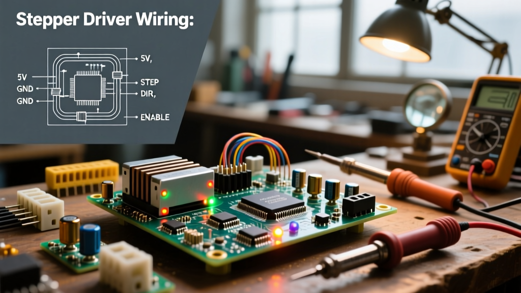
- The Driver: The legacy A4988 is obsolete for precision work. The BigTreeTech TMC2209 V1.2 ($12–$15) utilizes StealthChop2 for silent operation and SpreadCycle for high-speed dynamic accuracy, featuring 256-step microstepping interpolation.
- The Metrology Tool: You cannot calibrate what you cannot measure. A standard digital caliper is insufficient. Invest in a Mitutoyo 2046S Dial Indicator with 0.01mm resolution, mounted on a magnetic base, to measure actual carriage travel against the dial.
Stepper motors run hot by design, as current is constantly applied to hold position. As the copper windings heat up, resistance increases, altering the current profile and potentially causing missed microsteps. Always calibrate your system at its steady-state operating temperature (usually after 20 minutes of continuous movement), not when cold.
The Mathematics of Microstepping and Linear Translation
To write accurate Arduino code for stepper motor control, you must calculate the exact steps_per_mm (or steps per degree for rotary axes). The formula is straightforward but frequently miscalculated when gear reductions or belt pitches are introduced.
Base Formula: Steps per mm = (Motor Steps per Rev × Microstep Multiplier) / (Lead Screw Pitch or Belt Pulley Circumference)
For a standard 1.8° NEMA 17 (200 steps/rev) on a TMC2209 set to 16x microstepping, driving a TR8x2 lead screw (2mm pitch):
(200 × 16) / 2 = 1600 steps/mm
Driver Comparison for Accuracy (2026 Market)
| Driver IC | Max Interpolation | Current Sensing | Best Use Case | Avg Price |
|---|---|---|---|---|
| A4988 | 1/16 | Fixed Potentiometer | Low-cost prototyping | $4.50 |
| DRV8825 | 1/32 | Fixed Potentiometer | Higher torque, basic CNC | $6.00 |
| TMC2209 | 1/256 | Dynamic (StallGuard) | Precision 3D printing, lab automation | $13.50 |
According to Analog Devices (Trinamic), microstepping beyond 1/16 does not necessarily increase physical step resolution due to magnetic hysteresis and detent torque, but it drastically smooths the current waveform, reducing resonance and improving overall positional accuracy.
Optimized Arduino Code for Stepper Motor Calibration
Using the standard Stepper.h library is a mistake for calibration. It lacks acceleration profiling, which causes the motor to stall and lose steps during the initial inertia-breaking phase. Instead, we use the industry-standard AccelStepper library by Mike McCauley.
The following script is designed specifically for the calibration process. It moves the axis a precise commanded distance, allowing you to measure the physical result with your dial indicator.
#include <AccelStepper.h>

// Define the stepper and the pins it's connected to
// Using DRIVER interface (1) for Step/Dir modules like TMC2209
#define MOTOR_INTERFACE_TYPE 1
#define STEP_PIN 3
#define DIR_PIN 4

AccelStepper stepper(MOTOR_INTERFACE_TYPE, STEP_PIN, DIR_PIN);

// CALIBRATION VARIABLES
const float COMMAND_DISTANCE_MM = 100.0; // Commanded travel distance
const float STEPS_PER_MM = 1600.0;       // Theoretical steps per mm

void setup() {
  Serial.begin(115200);

  // Set speed and acceleration limits
  // High acceleration can cause skipped steps during calibration
  stepper.setMaxSpeed(2000);      // Steps per second
  stepper.setAcceleration(500);   // Steps per second squared

  // Initialize position
  stepper.setCurrentPosition(0);
  Serial.println("Calibration Routine Ready.");
  Serial.println("Move to home, then send '1' to begin 100mm test.");
}

void loop() {
  if (Serial.available() > 0) {
    char cmd = Serial.read();
    if (cmd == '1') {
      long targetSteps = COMMAND_DISTANCE_MM * STEPS_PER_MM;
      Serial.print("Moving ");
      Serial.print(COMMAND_DISTANCE_MM);
      Serial.println(" mm...");

      stepper.moveTo(targetSteps);

      // Blocking run to ensure exact positioning before measurement
      stepper.runToPosition();
      Serial.println("Movement Complete. Measure physical distance.");
    }
    else if (cmd == '0') {
      // Return to zero for repeated testing
      stepper.moveTo(0);
      stepper.runToPosition();
      Serial.println("Returned to Zero.");
    }
  }
}
The Dial Indicator Calibration Protocol
With the hardware wired and the code uploaded, execute the following physical calibration protocol to derive your true STEPS_PER_MM value. This methodology mirrors the Marlin Firmware M92 G-code calibration standards used in professional 3D printing.
- Pre-Heat the System: Run a continuous back-and-forth script for 15 minutes to bring the motor windings and lead screw to thermal equilibrium.
- Zero the Indicator: Command the motor to the start position. Press the dial indicator plunger against the moving carriage and zero the dial.
- Execute the Move: Send the
'1'command via the Serial Monitor to execute the 100mm move. - Measure and Record: Read the dial indicator. Suppose the dial reads
99.82 mm. The axis under-traveled. - Calculate the True Value: Use the correction formula:
New Steps/MM = (Old Steps/MM × Commanded Distance) / Actual Measured DistanceNew Steps/MM = (1600 × 100) / 99.82 = 1602.88 - Iterate: Update the
STEPS_PER_MMvariable in the Arduino code, re-upload, and repeat the test until the dial indicator reads exactly100.00 mm(within a 0.02mm tolerance).
Troubleshooting Edge Cases: When Code Meets Physics
If your calibration yields inconsistent results (e.g., the dial reads 100.1mm on one run and 99.6mm on the next), you are experiencing mechanical or electrical failure modes. Code cannot fix physics.
1. Mid-Band Resonance
Stepper motors suffer from a phenomenon called mid-band resonance, typically occurring between 150 and 300 RPM. At this speed, the rotor overshoots and undershoots the magnetic poles, causing severe vibration and lost steps. Solution: Increase the acceleration in your Arduino code to pass through the resonant RPM band faster, or enable the TMC2209's SpreadCycle mode via UART to dynamically adjust current and dampen resonance.
2. Insufficient Current (VREF Tuning)
If the motor stalls during the acceleration phase of the runToPosition() command, the driver is likely starved of current. Solution: Measure the VREF voltage on the driver's potentiometer (or configure via UART for TMC drivers). For a 1.68A rated LDO motor, set the RMS current to approximately 1.2A (70% of peak) to prevent thermal shutdown while maintaining holding torque.
3. Backlash and Lead Screw Play
If your axis is accurate when moving in one direction but consistently off by 0.1mm to 0.3mm when reversing, you are measuring mechanical backlash, not motor inaccuracy. Solution: Calibrate using only unidirectional moves (always approach the measurement point from the same direction) and install anti-backlash nuts with spring-loaded Delrin or POM inserts on your lead screws.
Final Thoughts on Metrology
Writing robust Arduino code for stepper motor applications requires an understanding that software commands are only as good as the physical system executing them. By combining the trapezoidal acceleration profiling of the AccelStepper library with rigorous dial-indicator metrology and modern chopper drivers like the TMC2209, you elevate your DIY projects from hobbyist prototypes to precision instruments capable of sub-millimeter repeatability.