
The Illusion of analogWrite() and Hardware PWM
Most introductory electronics tutorials treat analogWrite(pin, value) as a simple, foolproof way to dim LEDs or control motor speed. However, under the hood of the classic Arduino Uno R3 (ATmega328P), this function is merely an abstraction layer over Arduino hardware PWM (Pulse Width Modulation). By relying on the Arduino core's default configuration, you are locked into fixed frequencies—typically 490 Hz or 980 Hz. While sufficient for basic LED dimming, these default frequencies cause audible whining in DC motors, introduce jitter in precision analog filtering, and create visible flicker in persistence-of-vision (POV) displays.
To achieve true, jitter-free signal generation and unlock high-frequency motor control (20 kHz+), you must bypass the Arduino core and manipulate the microcontroller's hardware timers directly. This guide covers the exact wiring, timer-to-pin mapping, and C++ register code required to master hardware PWM on AVR-based boards, alongside critical architectural shifts seen in modern 2026 development environments.
The ATmega328P Timer-to-Pin Mapping Matrix
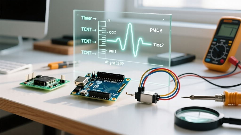
Hardware PWM is not generated by software loops; it is handled by dedicated silicon peripherals called Timers. The ATmega328P features three distinct timers, each mapped to specific physical I/O pins. Understanding this matrix is critical to avoid catastrophic library collisions.
| Timer Peripheral | Bit-Width | Mapped Pins (Uno R3) | Default Core Freq | Core Dependencies & Conflicts |
|---|---|---|---|---|
| Timer0 | 8-bit | D5, D6 | ~976 Hz | CRITICAL: Powers millis(), delay(), and micros(). Altering this timer breaks system timing. |
| Timer1 | 16-bit | D9, D10 | ~490 Hz | Hijacked by the Servo.h library. Ideal for high-resolution, custom-frequency PWM. |
| Timer2 | 8-bit | D3, D11 | ~490 Hz | Used by the tone() and pulseIn() functions. |
Expert Insight: Never attempt to change the prescaler or waveform generation mode of Timer0 unless you are writing a bare-metal RTOS and intend to rewrite the system tick interrupt handler. For custom hardware PWM, Timer1 (16-bit) is your primary target due to its superior resolution (up to 65,536 steps compared to the 256 steps of 8-bit timers).
Wiring for High-Frequency Motor Control
When driving inductive loads like DC motors or solenoids, the default 490 Hz PWM frequency falls squarely in the human hearing range, resulting in an annoying high-pitched whine. By pushing the hardware PWM frequency to 20 kHz (ultrasonic), we eliminate acoustic noise and improve the thermal efficiency of the motor windings.
The TB6612FNG vs. L298N Reality
In legacy tutorials, the L298N BJT-based motor driver is ubiquitous. In 2026, using an L298N for precision hardware PWM is a critical error. The L298N suffers from a ~2.0V voltage drop across its Darlington pairs and requires massive heat sinking. Instead, we wire the TB6612FNG MOSFET-based driver (typically $1.50 - $3.00 on component marketplaces). It handles 1.2A continuous current per channel with a negligible 0.5V drop, preserving your battery voltage and allowing the fast rise/fall times required for 20 kHz+ PWM signals without waveform distortion.
Step-by-Step Wiring (Timer1 / Pin D9)
- VM (Motor Voltage): Connect to your external power supply (e.g., 12V LiPo pack).
- VCC (Logic Voltage): Connect to Arduino 5V.
- GND: Tie the TB6612FNG GND, Arduino GND, and external power supply GND together. Shared ground is mandatory for logic-level signal integrity.
- PWMA: Connect directly to Arduino Pin D9 (Timer1, Channel A).
- AIN1 & AIN2: Connect to Arduino D4 and D7 for directional logic.
- STBY: Tie to VCC (5V) to keep the driver permanently enabled.
- AO1 & AO2: Connect to the DC motor terminals.
Bypassing the Arduino Core: Direct Register Code
To generate a 20 kHz signal on Pin D9, we must configure Timer1 for Phase and Frequency Correct PWM mode. This mode counts up to a TOP value, then counts back down, providing symmetrical pulses that are highly preferred for motor control and H-bridge drivers to prevent shoot-through currents.
The Math Behind the Registers
The formula for Phase Correct PWM frequency is:
f = f_clk / (2 × N × TOP)
- f_clk = 16,000,000 Hz (Arduino Uno crystal)
- N = Prescaler (We will use 1 for maximum resolution)
- f = 20,000 Hz (Target ultrasonic frequency)
Solving for TOP: TOP = 16,000,000 / (2 × 1 × 20,000) = 400.
Because the timer counts from 0 to TOP, we set the ICR1 register to 399. This yields exactly 400 steps of duty cycle resolution (0-399), which is more than adequate for smooth motor ramping.
Implementation Code
// Direct Hardware PWM Configuration for 20kHz on Pin D9 (Timer1)

void setup() {
  pinMode(9, OUTPUT);  // OC1A pin
  pinMode(4, OUTPUT);  // AIN1 (Direction)
  pinMode(7, OUTPUT);  // AIN2 (Direction)

  // Clear Timer1 control registers
  TCCR1A = 0;
  TCCR1B = 0;

  // Set Phase and Frequency Correct PWM mode
  // WGM13 = 1, WGM12 = 0, WGM11 = 0, WGM10 = 0
  TCCR1B |= (1 << WGM13);

  // Set non-inverting mode on OC1A (Pin D9)
  // COM1A1 = 1, COM1A0 = 0
  TCCR1A |= (1 << COM1A1);

  // Set prescaler to 1 (starts the timer)
  // CS11 = 0, CS10 = 1
  TCCR1B |= (1 << CS10);

  // Set TOP value for 20kHz frequency
  ICR1 = 399;

  // Set initial duty cycle to 0 (Motor stopped)
  OCR1A = 0;

  // Set motor direction forward
  digitalWrite(4, HIGH);
  digitalWrite(7, LOW);
}

void loop() {
  // Ramp motor up smoothly using the 400-step resolution
  for (int i = 0; i <= 399; i++) {
    OCR1A = i;         // Update hardware PWM duty cycle
    delay(10);         // 10ms delay for visual/mechanical ramping
  }

  delay(2000);         // Hold at max speed

  // Ramp down
  for (int i = 399; i >= 0; i--) {
    OCR1A = i;
    delay(10);
  }
  delay(2000);
}
Critical Edge Cases and Library Collisions
When integrating hardware PWM into larger robotics projects, you will inevitably encounter peripheral collisions. The most common failure mode in Arduino ecosystems is the Servo Library Conflict.
The standard Arduino Servo library requires a highly precise 50 Hz signal (20ms period). To achieve this without blocking the main CPU loop, the library automatically hijacks Timer1 upon calling Servo.attach(). If you have configured Timer1 for 20 kHz motor control, attaching a servo will instantly overwrite your TCCR1A/B registers, dropping your motor PWM to 50 Hz and likely causing your motor driver to overheat or the motor to stall violently.
The Solution: If your project requires both high-frequency motor PWM and RC servos, you must migrate your motor control to Timer2 (Pins D3/D11), or utilize a dedicated hardware PWM generator like the PCA9685 (I2C) for the servos, leaving Timer1 strictly for your DC motors.
The 2026 Landscape: Migrating to ARM and ESP32
While the ATmega328P remains the gold standard for learning bare-metal timer manipulation, modern prototyping has largely shifted toward 32-bit architectures. If you are deploying hardware PWM in a 2026 production environment, you are likely using an ESP32-S3 or the Arduino Uno R4 Minima.
- ESP32 (LEDC Peripheral): The ESP32 does not use AVR timers. It features a dedicated LED Control (LEDC) peripheral capable of generating hardware PWM on almost any GPIO pin. Configuration is handled via the
ledcSetup(channel, freq, resolution)API, completely abstracting the register math while maintaining hardware-level jitter immunity. - Arduino Uno R4 (Renesas RA4M1): The R4 architecture utilizes the Advanced General Timer (AGT). Direct AVR register manipulation (
TCCR1A) will result in compilation errors. Developers must use theFspTimerlibrary or rely on the enhancedanalogWriteResolution(12)core functions to achieve 12-bit hardware PWM.
For deep-dive reference material on AVR timer architectures and bare-metal register mapping, consult the official Microchip ATmega328P datasheet and the industry-standard Nick Gammon Timer Guide. Mastering these hardware-level concepts ensures your designs remain robust, efficient, and immune to the timing jitter that plagues software-based PWM implementations.