
Beyond the Breadboard: Deploying the DHT11 in the Real World
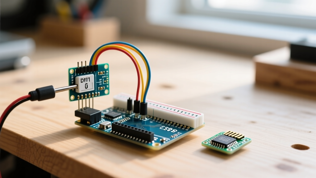
The DHT11 is universally recognized as the 'Hello World' of environmental sensing. However, transitioning a dht11 sensor with arduino project from a controlled desk environment to a real-world application—like a high-humidity reptile terrarium or a seedling propagation chamber—exposes the hardware's hidden quirks. While the sensor is incredibly cost-effective, its custom single-bus protocol, strict timing requirements, and susceptibility to electrical noise demand a rigorous engineering approach.
In this guide, we will design a robust thermal and humidity exhaust controller for a 40-gallon reptile enclosure. We will bypass generic tutorial advice and focus on the actual failure modes: interrupt service routine (ISR) timing collisions, long-wire capacitance degradation, and high-humidity PCB corrosion.
2026 Component Selection and Budget
Building a reliable climate controller requires selecting components that can handle continuous 24/7 operation. Below is the optimized Bill of Materials (BOM) based on current 2026 market pricing for hobbyist-grade, high-reliability components.
| Component | Specification | Est. Cost (USD) | Real-World Justification |
|---|---|---|---|
| Microcontroller | Arduino Nano V3.0 (ATmega328P) | $6.50 | Small footprint, 5V logic natively matches DHT11 without level shifting. |
| Sensor | DHT11 3-Pin Module | $2.80 | Includes onboard 4.7kΩ pull-up and power filtering capacitor. |
| Actuator | 5V Relay Module (Opto-isolated) | $3.20 | Opto-isolation prevents relay coil EMI from resetting the Arduino. |
| Wiring | 22AWG Stranded Silicone | $8.00/spool | High strand count prevents breakage from repeated enclosure door movements. |
| Protection | MG Chemicals Silicone Conformal Coating | $14.50 | Prevents sulfidation and shorting in 70%+ RH environments. |
Bare Sensor vs. Pre-Wired Module
When sourcing your dht11 sensor with arduino, you will encounter two variants: the bare 4-pin blue plastic sensor and the 3-pin PCB module. For permanent installations, always choose the 3-pin module. The bare sensor requires you to manually solder a 4.7kΩ to 10kΩ pull-up resistor between VCC and the DATA pin. The module integrates this resistor alongside a 100nF decoupling capacitor, which is critical for filtering out high-frequency noise generated by nearby relay switching or LED lighting ballasts.
Wiring Physics: The Pull-Up Resistor and Cable Capacitance
The DHT11 does not use I2C or standard Dallas 1-Wire; it uses a proprietary single-bus protocol where the MCU and sensor take turns pulling the data line low. The line is pulled high by a resistor. This is where most real-world builds fail.
Engineering Rule of Thumb: The DHT11 data line relies on an RC (resistor-capacitor) circuit formed by the pull-up resistor and the parasitic capacitance of your wire. If your wire is too long, the voltage rise time becomes too slow, and the Arduino misreads the microsecond-level pulses as logic errors.
If you are running a cable longer than 1.5 meters from the Arduino Nano to the terrarium sensor probe, the standard 4.7kΩ pull-up resistor on the module will result in 'Checksum Error' or 'Timeout' faults. To fix this, you must lower the pull-up resistance to compensate for the added wire capacitance. Solder an additional 4.7kΩ resistor in parallel with the module's existing resistor to achieve a ~2.3kΩ pull-up. This steepens the rising edge of the signal, ensuring the ATmega328P accurately captures the 20-40µs pulse widths.
For authoritative details on how microcontrollers handle internal and external pull-up configurations, refer to the Arduino Digital Pins Documentation.
The Hidden Software Trap: ISR Timing Collisions
The most frustrating issue when deploying a DHT11 in a complex Arduino sketch is random read failures that only occur when the system is under load. This is rarely a hardware fault; it is an Interrupt Service Routine (ISR) timing collision.
The DHT11 read sequence takes approximately 4 milliseconds. During this window, the sensor outputs 40 bits of data by toggling the data line high and low with precise microsecond timing. If your Arduino sketch uses PWM (Pulse Width Modulation) to dim terrarium heat lamps, or if you are using a timer-based library to update an LCD display, an interrupt will pause the main loop. If the DHT library is waiting for a pin state change and an ISR delays the CPU by even 50 microseconds, the bitstream falls out of sync, resulting in a failed read.
Implementing the Software Fix
To guarantee reliable reads, you must temporarily disable interrupts during the 4ms sensor polling window. If you are using the widely adopted Adafruit DHT library, you can wrap the read function to prevent ISR interference:
- Call
noInterrupts()immediately before triggering the DHT read function. - Execute the
dht.read11()ordht.readTemperature()function. - Call
interrupts()immediately after the read completes.
Warning: Disabling interrupts for 4ms will cause slight jitter in PWM outputs and software serial communication. In a terrarium controller, a 4ms jitter on a heat lamp PWM signal is thermally imperceptible, making this a highly acceptable trade-off for 100% data reliability.
For a deeper dive into the underlying protocol timing and electrical characteristics of the DHT series, the Adafruit DHT Sensor Guide remains the definitive community resource.
Environmental Protection in High-Humidity Enclosures
Reptile enclosures and propagation tents frequently operate at 60% to 80% Relative Humidity (RH). While the DHT11's blue plastic cap is designed to let air pass through to the internal thermistor and capacitive humidity sensor, the exposed copper traces and solder joints on the PCB module are highly vulnerable to galvanic corrosion and dendritic growth.
Actionable Protection Steps:
- Mask the Sensor Cap: Use Kapton tape to tightly cover the blue plastic sensor cap and the small breathing holes.
- Apply Conformal Coating: Paint the PCB traces, solder joints, and resistor legs with a silicone-based conformal coating. Avoid acrylic coatings, as they can trap moisture underneath if applied imperfectly.
- Create a Drip Loop: When routing the 22AWG silicone wire into the enclosure, ensure the wire dips below the sensor module before rising to the Arduino. This prevents condensation from wicking down the wire and pooling on the PCB.
Sensor Upgrade Matrix: When the DHT11 Isn't Enough
The DHT11 is perfectly adequate for maintaining a basking spot between 28°C and 32°C with moderate humidity. However, if your application requires extreme precision or operation outside its narrow physical limits, you must upgrade. Below is a real-world comparison matrix to guide your peripheral selection.
| Feature | DHT11 (Budget) | DHT22 / AM2302 (Standard) | SHT31-D (Professional) |
|---|---|---|---|
| Temperature Range | 0°C to 50°C | -40°C to 80°C | -40°C to 125°C |
| Temp Accuracy | ± 2.0°C | ± 0.5°C | ± 0.2°C |
| Humidity Range | 20% to 80% RH | 0% to 100% RH | 0% to 100% RH |
| Sample Rate | 1 Hz (1 sec) | 0.5 Hz (2 sec) | Up to 10 Hz (I2C) |
| Protocol | Custom Single-Bus | Custom Single-Bus | Standard I2C |
| Approx. Cost (2026) | $2.80 | $5.50 | $9.00 |
If you are building a desert scorpion enclosure requiring 20% RH and 45°C ambient heat, the DHT11 will fail to register accurately. Upgrade to the DHT22. If you are logging rapid thermal changes in a server rack, the 1Hz limit of the DHT series will bottleneck your data; upgrade to the I2C-based SHT31-D.
Frequently Asked Questions (Edge Cases)
Why does my DHT11 read 'NaN' on the first boot?
The DHT11 requires a stabilization period of up to 2 seconds after power is applied before its internal capacitor is fully charged and its ADC is calibrated. If your Arduino sketch attempts to read the sensor in the setup() loop immediately after power-on, it will return 'NaN' (Not a Number). Always implement a delay(2000) at the end of your setup routine before the first read.
Can I power the DHT11 from an Arduino digital pin to save battery?
While the DHT11 draws only ~1mA during a read and <100µA in standby, powering it via a digital pin is not recommended for long-wire runs. The ATmega328P digital pin has a maximum current sourcing limit, and the inrush current to charge the module's decoupling capacitor can cause a momentary voltage sag, corrupting the first data packet. Always power the module from the dedicated 5V rail.
My relay clicks rapidly when the temperature hovers around the setpoint.
This is known as 'chatter' or 'short-cycling,' and it will destroy your relay contacts and burn out your heat lamp prematurely. You must implement software hysteresis. If your target is 30°C, program the relay to turn ON at 29.0°C and turn OFF at 31.0°C. This 2-degree deadband prevents rapid cycling caused by the DHT11's ±2°C accuracy variance.