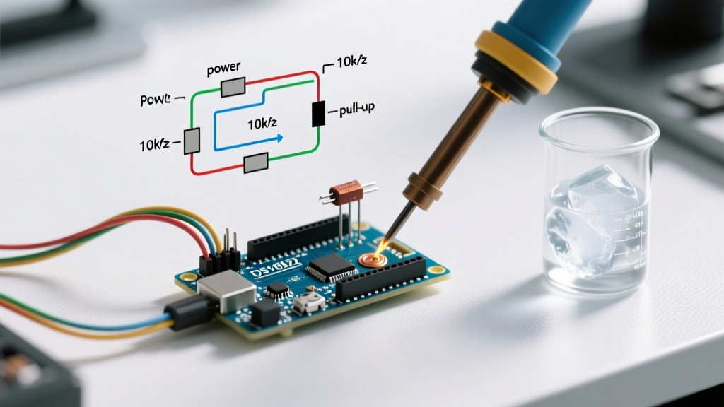

The Tolerance Illusion: Why Factory Specs Fail in the Field
Most hobbyists and embedded engineers plug an arduino temperature sensor into a breadboard, run a standard library, and blindly trust the serial monitor output. In 2026, with the rise of high-fidelity environmental monitoring for indoor agriculture, incubators, and server rack thermal management, accepting a default ±2°C error margin is no longer viable. The reality of semiconductor manufacturing means that factory calibration curves are based on statistical averages, not individual unit guarantees.
Before attempting calibration, you must understand the baseline limitations of your specific hardware. Below is a real-world accuracy matrix comparing popular sensors available on the market today, contrasting their datasheet claims with observed field drift.
| Sensor Model | Interface | Datasheet Tolerance | Real-World Drift (Uncalibrated) | Avg. Cost (2026) |
|---|---|---|---|---|
| DS18B20 (Genuine Analog Devices) | 1-Wire | ±0.5°C (-10 to +85°C) | ±0.7°C | $4.85 |
| DS18B20 (AliExpress Clone) | 1-Wire | N/A (Counterfeit) | ±2.5°C to 5.0°C | $1.20 |
| TMP36 (Analog Output) | Analog (ADC) | ±1.0°C (+25°C) | ±3.5°C (due to USB VBUS noise) | $1.95 |
| BME280 (Bosch Sensortec) | I2C / SPI | ±0.5°C (0 to +65°C) | ±1.2°C (PCB self-heating) | $6.50 |
| PT100 RTD + MAX31865 | SPI | ±0.1°C | ±0.3°C (Lead wire resistance) | $18.50 |
Root Causes of Sensor Drift and Inaccuracy
To calibrate effectively, you must isolate the physical or electrical phenomena causing the inaccuracy. An arduino temperature sensor rarely drifts due to the silicon itself; the error is almost always introduced by the surrounding circuit or environmental coupling.
1. USB VBUS Ripple and ADC Noise (Analog Sensors)
Analog sensors like the TMP36 or LM35 output a linear voltage (e.g., 10mV/°C for the TMP36). When powered via an Arduino Uno's 5V USB pin, switching noise from the host PC's power supply introduces ripple. A mere 50mV of ripple on the 5V line translates directly into a 5.0°C error in your reading. Furthermore, the default ATmega328P analog reference (DEFAULT) ties the ADC to this noisy 5V rail, compounding the error.
2. Parasite Power Timeout (1-Wire Sensors)
The Analog Devices DS18B20 official product page outlines a "parasite power" mode where the sensor draws power from the data line during conversion. If the Arduino's GPIO pin cannot supply enough current, or if the pull-up resistor is too weak (e.g., using 10kΩ instead of the required 4.7kΩ), the sensor resets mid-conversion and defaults to outputting exactly 85.0°C.
3. Thermal Coupling and Self-Heating (I2C Sensors)
Environmental sensors like the Bosch Sensortec BME280 are highly sensitive to PCB heat. If the sensor is mounted directly above an Arduino voltage regulator or an ESP32 Wi-Fi SoC, thermal conduction through the FR4 fiberglass will artificially inflate the temperature reading by 1.5°C to 3.0°C.
The Metrology-Grade Calibration Protocol
Calibrating an arduino temperature sensor requires establishing two fixed physical points: the ice point (0°C) and the steam point (100°C, adjusted for altitude). Relying on ambient room temperature compared to a cheap wall thermometer is a circular fallacy that guarantees inaccuracy.
Step 1: The NIST-Traceable Ice Bath Slurry
Dropping a sensor into a glass of ice water is insufficient. The water at the top of the glass will be 4°C, while the ice cubes themselves may be -15°C. To achieve a true 0.0°C reference, follow NIST Thermodynamic Temperature metrology guidelines for ice-point preparation:
- Crush the Ice: Use distilled water ice, crushed into fine chips (no larger than 1cm).
- Create a Slurry: Mix the crushed ice with distilled water in an insulated thermos. The ratio should be roughly 70% ice to 30% water.
- Stir and Equilibrate: Stir vigorously with a non-conductive rod. Allow the mixture to sit for 15 minutes.
- Submerge the Sensor: Ensure the active sensing element is fully submerged but not touching the bottom or sides of the thermos. Record the raw ADC or digital output.
Step 2: The Boiling Point Correction
Water only boils at exactly 100.0°C at standard atmospheric pressure (101.325 kPa or 1 ATM). If you live in Denver, Colorado (elevation 1,609m), water boils at approximately 94.6°C. You must calculate the true boiling point for your exact barometric pressure on the day of calibration using a local meteorological station's data, then suspend the sensor in the steam (not the rolling water, which can contain superheated pockets) above the boiling liquid.
Hardware-Level Accuracy Hacks
Software offsets can only do so much. True precision requires hardware intervention, particularly when dealing with the ATmega328P's 10-bit Analog-to-Digital Converter (ADC).
Pro-Tip: The AREF Voltage Hack
By default, the Arduino Uno maps 0-5V to ADC values 0-1023, yielding a resolution of 4.88mV per step. For a TMP36 (10mV/°C), one ADC step equals nearly 0.5°C. By feeding a clean 3.3V from an external Low Dropout (LDO) regulator into theAREFpin and settinganalogReference(EXTERNAL)in your code, you drop the step size to 3.22mV, instantly doubling your temperature resolution to ~0.3°C per step.
Decoupling and RC Filtering
For analog sensors, always place a 0.1µF ceramic capacitor directly across the VCC and GND pins of the sensor to filter high-frequency RF noise. Additionally, adding a 100Ω resistor in series with the analog output pin, followed by a 10µF tantalum capacitor to ground at the Arduino's analog input pin, creates a low-pass RC filter that smooths out transient spikes.
Software Calibration: Implementing the Steinhart-Hart Equation
If you are using an NTC thermistor rather than a linear IC, the resistance-to-temperature curve is highly non-linear. The Beta parameter equation is only accurate over a narrow 25°C to 50°C window. For wide-range accuracy, you must implement the Steinhart-Hart equation:
1/T = A + B(ln R) + C(ln R)^3
Where T is temperature in Kelvin, R is resistance in Ohms, and A, B, C are coefficients specific to your exact thermistor batch. To derive these coefficients, measure the resistance of your thermistor at three distinct, widely-spaced temperatures (e.g., 0°C ice bath, 25°C room temp, and 60°C heated oil bath), then solve the system of three linear equations. Most modern 2026 thermistor libraries for the Arduino ecosystem include a built-in Steinhart-Hart coefficient calculator if you input these three raw resistance values.
Troubleshooting Edge Cases and Failure Modes
Even with perfect calibration, edge cases will ruin your data logging. Use this diagnostic matrix to solve anomalous readings:
| Symptom | Root Cause | Engineering Fix |
|---|---|---|
| DS18B20 reads exactly 85.0°C on startup | Parasite power voltage droop during conversion. | Switch to VDD external power mode. Wire pin 3 to 3.3V/5V instead of GND. |
| TMP36 fluctuates ±3°C randomly | ADC sampling noise / unshielded long wires. | Implement oversampling in software (read 64 times, bit-shift right by 2) and add local RC filtering. |
| BME280 reads 2.5°C higher than ambient | PCB self-heating from continuous I2C polling. | Set sensor to forced mode. Trigger single read, then return to sleep mode for 5 seconds between samples. |
| Readings drop when a relay switches on | Inductive kickback causing brownout on VCC rail. | Use an opto-isolated relay module with a completely separate power supply for the relay coils. |
Final Thoughts on Sensor Selection
Calibration can correct offset and gain errors, but it cannot fix a sensor with poor repeatability or hysteresis. If your project requires ±0.1°C stability for medical or chemical applications, abandon the TMP36 and standard DS18B20 entirely. Invest in a 3-wire or 4-wire PT100 RTD paired with a MAX31865 breakout board. The 4-wire Kelvin connection completely eliminates lead-wire resistance errors, providing laboratory-grade accuracy that software calibration alone could never achieve on a standard microcontroller ADC.