
Introduction to Arduino Display Interfacing
Adding visual feedback to your microcontroller projects is a major milestone for any DIY electronics enthusiast. Whether you are building a weather station, a smart home controller, or a simple digital clock, an Arduino display transforms abstract serial monitor data into tangible, real-world information. For beginners, the sheer volume of display technologies—ranging from 7-segment LEDs to high-resolution TFT touchscreens—can be overwhelming.
This tutorial focuses on the most practical, cost-effective, and beginner-friendly entry point into visual interfacing: the I2C OLED and I2C LCD modules. By leveraging the I2C (Inter-Integrated Circuit) communication protocol, we reduce complex parallel wiring down to just four pins, minimizing hardware headaches and allowing you to focus on writing functional code. As of 2026, the I2C standard remains the undisputed backbone of low-speed peripheral communication in the maker space.
Choosing Your First Arduino Display: Market Snapshot
Before soldering or plugging in jumper wires, it is crucial to select the right display for your project constraints. Below is a comparison of the three most common beginner displays available on the market today.
| Display Type | Controller Chip | Resolution | Avg. Cost (2026) | Best Use Case |
|---|---|---|---|---|
| 0.96" Monochrome OLED | SSD1306 | 128 x 64 | $4.00 - $5.50 | Icons, graphs, crisp text, battery-powered projects |
| 16x2 Character LCD | HD44780 + I2C Backpack | 16 chars x 2 lines | $3.50 - $5.00 | Simple text readouts, indoor appliances, high-visibility |
| 1.3" IPS TFT LCD | ST7789 | 240 x 240 | $7.00 - $9.50 | Color UI, images, advanced dashboards (requires SPI) |
Recommendation: For this tutorial, we will focus heavily on the 0.96" SSD1306 I2C OLED. It offers superior contrast, requires no backlight (saving power), and supports both text and basic graphics, making it the ultimate versatile Arduino display for beginners.
The Hardware: Wiring the SSD1306 I2C OLED
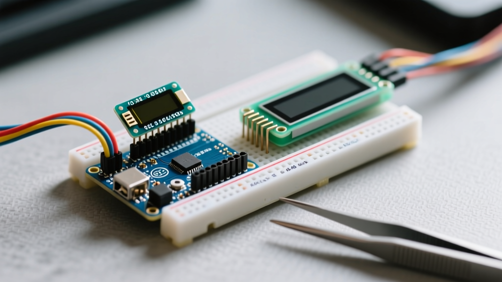
The primary advantage of an I2C Arduino display is the minimal pin count. Unlike older parallel interfaces that required up to 12 digital pins, I2C uses a shared bus architecture requiring only Serial Data (SDA) and Serial Clock (SCL) lines, plus power and ground.
Pinout Matrix for Common Microcontrollers
Wiring the display correctly is critical. A common beginner mistake is connecting SDA and SCL to arbitrary digital pins. You must use the hardware I2C pins native to your specific board to ensure reliable communication speeds.
| OLED Pin | Arduino Uno R3 / Nano | ESP32 DevKit V1 | Arduino Nano 33 IoT |
|---|---|---|---|
| GND | GND | GND | GND |
| VCC | 5V | 3.3V | 3.3V |
| SCL | A5 | GPIO 22 | D12 (SCL) |
| SDA | A4 | GPIO 21 | D11 (SDA) |
Expert Note on Pull-Up Resistors: The I2C protocol requires pull-up resistors on the SDA and SCL lines. Almost all commercial SSD1306 breakout boards include 4.7kΩ surface-mount pull-up resistors tied to VCC. If you are daisy-chaining multiple I2C devices, the parallel resistance may drop too low (below 2kΩ), causing signal degradation. In such cases, you may need to desolder the resistors on the secondary modules.
Software Setup: The U8g2 Library Standard
While Adafruit's SSD1306 library is popular, the U8g2 library by Oliver Kraus is widely considered the gold standard for monochrome displays in 2026. It supports over 100 different display controllers, offers a massive selection of built-in fonts, and handles memory buffering highly efficiently. You can explore the full documentation on the official U8g2 GitHub repository.
Installation Steps:
- Open the Arduino IDE.
- Navigate to Sketch > Include Library > Manage Libraries.
- Search for
U8g2and install the package authored by Oliver Kraus.
Writing Your First "Hello World" Sketch
Below is a minimal, fully functional sketch to initialize the display and render text. Notice the constructor line—this tells the library exactly which hardware you are using and how it is oriented.
#include <Arduino.h>
#include <U8g2lib.h>
#include <Wire.h>

// Constructor for 0.96" SSD1306 128x64 I2C OLED
// U8G2_R0 sets rotation to 0 degrees. U8X8_PIN_NONE disables hardware reset.
U8G2_SSD1306_128X64_NONAME_F_HW_I2C u8g2(U8G2_R0, U8X8_PIN_NONE);

void setup() {
  Wire.begin();
  u8g2.begin();
}

void loop() {
  u8g2.clearBuffer(); // Clear the internal memory buffer
  u8g2.setFont(u8g2_font_ncenB08_tr); // Set a bold, readable font
  u8g2.drawStr(0, 24, "Electrical Flux!"); // Draw string at X=0, Y=24
  u8g2.drawStr(0, 48, "I2C OLED Guide");
  u8g2.sendBuffer(); // Transfer memory buffer to the physical display

  delay(2000);
}
For a deeper understanding of how the Wire library handles the underlying I2C bus communication, refer to the official Arduino Wire Reference.
Real-World Troubleshooting & Edge Cases
Hardware rarely works perfectly on the first try. Here are the most common failure modes beginners encounter when interfacing an Arduino display, along with actionable solutions.
1. The "Blank Screen" I2C Address Mismatch
If your code compiles and uploads but the screen remains black, your I2C address is likely incorrect. The SSD1306 typically uses 0x3C, but many clone manufacturers alter the resistor configuration on the PCB to use 0x3D. Similarly, 16x2 LCDs with PCF8574 backpacks usually default to 0x27, while those with PCF8574A chips use 0x3F.
The Fix: Run an I2C Scanner sketch (available in the Arduino IDE under File > Examples > Wire > I2CScanner). Open the Serial Monitor at 115200 baud. The scanner will ping the bus and return the exact hexadecimal address of your connected display.
2. Logic Level Voltage Clashes (3.3V vs 5V)
Most generic SSD1306 OLEDs are rated for 3.3V logic but include an onboard LDO (Low Dropout) regulator allowing them to accept 5V on the VCC pin. However, if you connect a 5V Arduino Uno's SDA/SCL lines directly to a strictly 3.3V display (like certain high-res TFTs or bare OLED modules without regulators), you risk frying the display's controller chip.
The Fix: If you are using a 3.3V microcontroller (like an ESP32 or Arduino Nano 33 IoT), wire VCC to the 3.3V pin. If you must bridge a 5V MCU to a 3.3V display, use a bidirectional logic level converter (e.g., BSS138 MOSFET-based modules, costing around $1.50) on the SDA and SCL lines.
3. The LCD Contrast Potentiometer Trap
If you opt for the 16x2 I2C LCD instead of the OLED, a very common issue is seeing only the backlight illuminate with no visible text blocks. This is almost never a code issue.
The Fix: On the back of the I2C backpack, there is a small blue trimmer potentiometer. Using a small Phillips screwdriver, turn this pot slowly while the device is powered on. You will suddenly see the 5x8 pixel character blocks appear. Adjust until the background blocks are just barely invisible, leaving only the active text visible.
4. Flickering and Screen Tearing
If your display flickers during updates, you are likely using a "Page Buffer" or "Line Buffer" constructor in U8g2 (denoted by _1_ or _2_ in the class name) and calling sendBuffer() too frequently inside a fast loop.
The Fix: Always use the Full Buffer constructor (denoted by _F_, as used in our code example above). This allocates enough SRAM to hold the entire 128x64 frame (1024 bytes) in the microcontroller's memory, eliminating tearing by pushing the complete frame to the display in a single I2C transaction.
Summary & Next Steps
Mastering the Arduino display via I2C opens the door to complex, user-friendly DIY projects. By understanding the physical wiring constraints, utilizing the robust U8g2 library, and knowing how to troubleshoot I2C address and logic-level conflicts, you can confidently integrate visual feedback into any microcontroller build. Once you have text rendering working, explore the U8g2 XBM (X BitMap) drawing functions to add custom graphics and sensor-readout charts to your OLED interface.