
Why Physical Sensor Readouts Still Matter in 2026
In an era dominated by high-resolution TFT screens and cloud-based IoT dashboards, the humble seven segment display remains a staple in industrial and DIY sensor integration. Why? Because when you need to read a temperature, pressure, or flow rate from across a brightly lit workshop, a high-contrast, emissive LED display outperforms LCDs and OLEDs in both visibility and ruggedness. Integrating a seven segment display Arduino setup for sensor readouts provides a dedicated, low-latency physical interface that doesn't require a network connection or a smartphone to interpret.
However, driving these displays directly from a microcontroller involves specific electrical challenges. Whether you are reading an AHT20 temperature sensor or a BMP390 pressure module, failing to account for display multiplexing and current sinking can lead to flickering readouts, ghosting, or worse—a fried microcontroller pin. This guide details the exact hardware selection, electrical math, and integration strategies required to build a robust sensor-to-display pipeline.
Choosing Your Seven Segment Display Hardware
Before wiring a single jumper cable, you must decide how the display will be driven. As of 2026, the maker market has standardized around three primary approaches for physical numeric readouts. Below is a technical comparison of the most common modules used in sensor integration projects.
| Hardware Type | Example Model | Interface | MCU Pins Required | Avg. Cost (2026) | Best Use Case |
|---|---|---|---|---|---|
| Bare Common Cathode | Kingbright SC56-11GWA | Direct / Multiplexed | 8 (single) or 12 (quad) | $1.20 - $2.50 | Custom PCBs, low-level learning |
| SPI Driver Module | MAX7219 4-Digit | SPI | 3 (DIN, CS, CLK) | $3.50 - $5.00 | High-precision, no-flicker sensor arrays |
| Proprietary I2C-like | TM1637 4-Digit | Custom 2-Wire | 2 (CLK, DIO) | $1.80 - $2.50 | Rapid prototyping, simple temp readouts |
For most sensor integration tutorials, the TM1637 offers the best balance of cost and pin-efficiency. However, if your sensor requires strict SPI timing or you are building a commercial-grade prototype, the MAX7219 is vastly superior due to its hardware-level multiplexing and built-in current control. For a deep dive into shift-register based driving, refer to the official Arduino ShiftOut documentation.
The Physics of Current Limiting: Avoiding MCU Damage
A common catastrophic failure mode for beginners wiring bare seven segment displays to an Arduino Uno R3 or R4 Minima is ignoring the forward voltage (Vf) and maximum continuous forward current (If) of the LED segments.
Calculating Resistors for the Kingbright SC56-11GWA
Let us look at the exact math for a standard 0.56-inch green common-cathode display. According to the manufacturer datasheet, the green segments have a Vf of 2.2V and a recommended If of 20mA. If you are powering the display from the Arduino's 5V pin:
- Source Voltage (Vs): 5.0V
- Forward Voltage (Vf): 2.2V
- Target Current (If): 0.020A (20mA)
Using Ohm's Law (R = (Vs - Vf) / If):
R = (5.0 - 2.2) / 0.020 = 140Ω
Since 140Ω is not a standard E12 resistor value, you should round up to 150Ω to ensure you stay safely under the 20mA threshold. Never connect bare LED segments directly to an Arduino GPIO pin without a current-limiting resistor. Furthermore, if you are multiplexing a 4-digit display, the common cathode pin must sink the combined current of up to 8 segments simultaneously (8 x 20mA = 160mA). The ATmega328P and the RA4M1 (Uno R4) cannot handle 160mA on a single pin. You must use a switching transistor, such as a 2N2222 or a logic-level MOSFET like the IRLZ44N, to handle the common pin current.
The Multiplexing Trap: Software Blocking vs. Sensor Read Times
This is the most critical concept in sensor-to-display integration. Bare seven segment displays and basic shift-register setups require software multiplexing. This means the microcontroller must cycle power through each of the 4 digits sequentially, relying on Persistence of Vision (POV) to make them appear lit simultaneously. To avoid visible flicker, this cycle must repeat at least 60 times per second (every ~16ms total, or 4ms per digit).
Now, consider your sensor. The popular AHT20 temperature and humidity sensor requires an I2C trigger command, followed by a measurement delay. According to the AHT20 datasheet, the sensor takes approximately 75ms to 80ms to complete a read. If your Arduino code uses a blocking function (like delay(80) or a while loop waiting for the I2C data ready flag) to read the sensor, your display multiplexing stops completely for 80ms. The result? Three digits will go completely dark, and the active digit will burn dangerously bright because it is receiving 100% of the duty cycle.
Expert Integration Rule: Never use blocking delays when combining software-multiplexed displays with I2C/1-Wire sensors. Always use hardware-multiplexed driver chips (like the TM1637 or MAX7219) for sensor projects, or implement non-blocking timer interrupts for bare displays. The Texas Instruments MAX7219 datasheet explicitly details how its internal oscillator handles multiplexing independently of the host MCU, completely eliminating sensor-blocking flicker.
Step-by-Step: Wiring an AHT20 Sensor to a TM1637 Display
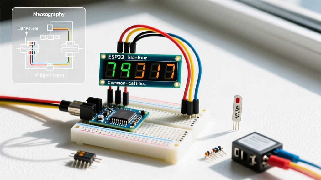
To bypass the multiplexing trap, we will use a TM1637 4-digit module. The TM1637 contains its own SRAM and multiplexing logic, meaning the Arduino only needs to send the sensor data once, freeing up the main loop to handle the AHT20's 80ms read delay without affecting the display.
Hardware Pinout Matrix
| Component | Pin Label | Arduino Uno R4 Minima Pin | Notes |
|---|---|---|---|
| AHT20 Sensor | VCC | 3.3V | AHT20 is strictly 3.3V logic! |
| AHT20 Sensor | GND | GND | Common ground required |
| AHT20 Sensor | SDA | A4 (SDA) | Requires 4.7kΩ pull-up to 3.3V |
| AHT20 Sensor | SCL | A5 (SCL) | Requires 4.7kΩ pull-up to 3.3V |
| TM1637 Display | VCC | 5V | Display can safely run on 5V |
| TM1637 Display | GND | GND | Common ground required |
| TM1637 Display | CLK | D2 | Digital pin 2 |
| TM1637 Display | DIO | D3 | Digital pin 3 |
Crucial Note on Logic Levels: The AHT20 operates at 3.3V, while the TM1637 and Arduino Uno R4 Minima's 5V pin operate at 5V. Because they are on separate buses (I2C for the sensor, proprietary serial for the display), no logic level shifter is required between the two peripherals. However, you must ensure the I2C pull-up resistors are tied to the 3.3V rail, not the 5V rail, to prevent degrading the AHT20 over time.
Troubleshooting Common Display Failures
Even with dedicated driver chips, environmental and electrical factors can degrade your sensor readout. Use this diagnostic checklist when your physical display fails to match your serial monitor output.
- Ghosting (Faint segments lighting up when they should be off): This occurs when the TM1637 or MAX7219 fails to discharge the parasitic capacitance in the LED matrix between multiplexing cycles. Fix: Ensure your wiring is under 15cm. Long jumper wires act as capacitors. If using a custom PCB, add a 100nF decoupling capacitor directly across the VCC and GND pins of the driver IC.
- Dimming Under Load: If your display dims exactly when a relay or motor activates in your circuit, you are experiencing voltage sag. Sensor modules and LED displays should not share the same raw 5V rail as inductive loads. Fix: Power the display and sensor via a dedicated buck converter (like an LM2596 module set to 5.0V) rather than relying on the Arduino's onboard linear regulator, which maxes out around 500mA.
- Stuck Readouts (Data not updating): If the serial monitor shows changing sensor values but the display remains frozen, your I2C bus may be locking up due to noise. Fix: Implement a software watchdog timer in your Arduino code to reset the I2C peripheral if the
Wire.endTransmission()function hangs for more than 100ms. For advanced I2C bus recovery techniques and LED driving architectures, the Adafruit LED Backpack engineering guide provides excellent insights into bus capacitance management.
Final Integration Thoughts
Integrating a seven segment display with an Arduino for sensor readouts is a masterclass in balancing electrical constraints with software timing. By selecting a hardware-multiplexed driver like the TM1637 or MAX7219, you isolate your display refresh rate from your sensor acquisition delays. Always respect the forward voltage limits of your specific LED modules, isolate inductive loads from your logic rails, and utilize proper pull-up resistors on your I2C sensor buses. With these parameters locked in, your physical sensor readouts will remain bright, stable, and highly legible in any environment.