
The Great Audio Misconception in Arduino Projects
When searching for a sensor sound arduino solution, the vast majority of beginner tutorials point toward the $1.50 KY-038 or generic electret microphone modules. These modules are ubiquitous in starter kits, but they harbor a fundamental hardware limitation that datasheets clearly expose: they cannot record audio waveforms. They are envelope detectors. If your goal is FFT analysis, voice recognition, or actual audio recording, you must upgrade to a digital MEMS microphone like the INMP441.
In this datasheet explainer, we will dissect the silicon behind the two most common sound sensors used in the Arduino ecosystem. By reading the actual component datasheets, we can bridge the gap between theoretical specifications and real-world wiring, code implementation, and failure modes in 2026.
Part 1: The $1.50 Illusion — Decoding the LM393 Datasheet
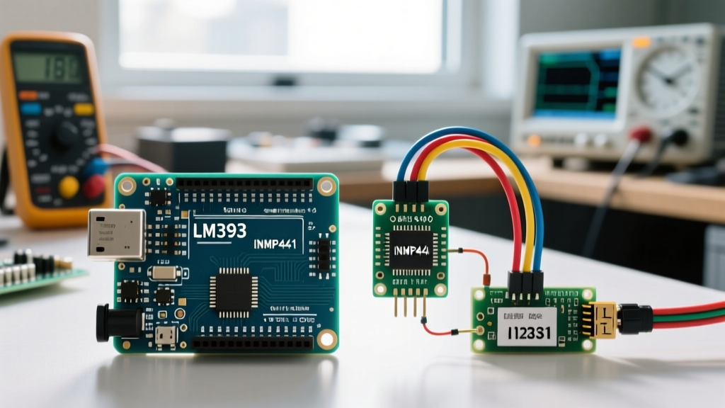
The standard analog/digital sound sensor module uses an electret microphone capsule paired with an LM393 dual differential comparator. The electret capsule captures acoustic pressure and converts it to a tiny analog voltage, which is amplified by an onboard op-amp. This signal is then fed into the LM393.
Why the LM393 is a Comparator, Not an ADC
According to the Texas Instruments LM393 Datasheet, the IC is designed to compare two input voltages and output a binary state, not a proportional analog value.
- Input Offset Voltage: Max 5mV. This means the comparator can reliably detect voltage differences as small as 5 millivolts between the audio signal and the reference voltage set by the module's blue trimpot.
- Response Time: 1.3 µs. While fast enough to trigger a digital interrupt when a loud clap occurs, it strips away all frequency and amplitude nuance.
- Output Type: Open-Collector. This is a critical datasheet detail. The D0 (Digital Out) pin does not actively drive HIGH. It only pulls LOW when the sound exceeds the threshold. It requires a pull-up resistor (typically 10kΩ to VCC) to register a HIGH state on your Arduino.
Expert Troubleshooting: If your Arduino's digitalRead() on the LM393 D0 pin is constantly floating or returning erratic 1s and 0s, your module likely lacks a sufficient pull-up resistor. Use pinMode(pin, INPUT_PULLUP); in your setup loop to activate the Arduino's internal 20kΩ pull-up, stabilizing the open-collector output.
Part 2: True Audio Sampling — The INMP441 MEMS Datasheet
To capture actual audio waveforms (e.g., 16kHz sample rate for voice, or 44.1kHz for music), you must bypass analog comparators entirely and use an I2S digital microphone. The INMP441 by TDK InvenSense is the industry standard for DIY audio, costing between $4.50 and $6.00 on breakout boards in 2026.
Translating MEMS Specs to Arduino Code
The INMP441 outputs a 24-bit I2S data stream. Let us break down the critical datasheet parameters that dictate how you write your Arduino audio buffers:
| Datasheet Parameter | Specification | Real-World Arduino Implication |
|---|---|---|
| Signal-to-Noise Ratio (SNR) | 61 dB (A-weighted) | Expect a noticeable noise floor in quiet rooms. Apply a software high-pass filter (above 80Hz) to eliminate HVAC rumble. |
| Sensitivity | -26 dBFS | The mic outputs digital values peaking at roughly 20% of the maximum 24-bit integer range during normal speech. You must apply a software gain multiplier (e.g., sample * 5) before processing. |
| Acoustic Overload Point | 116 dB SPL | Will clip heavily if placed directly next to a loudspeaker or inside a high-RPM drone chassis. |
| Interface | I2S (SCK, WS, SD) | Requires a hardware I2S peripheral. Standard 5V Arduino Unos lack this; you must use an Arduino Nano 33 IoT, Portenta, or ESP32. |
The L/R Pin: A Datasheet Trap
One of the most common failure modes when wiring the INMP441 is receiving a buffer full of zeros. The datasheet specifies that the L/R (Word Select) pin determines which stereo channel the mono microphone populates.
- If L/R is tied to GND, the microphone outputs data on the Left Channel (when the WS pin is LOW).
- If L/R is tied to VDD, it outputs on the Right Channel (when the WS pin is HIGH).
If your Arduino I2S Library is configured to read only the Left Channel, but you accidentally wired L/R to 3.3V, your audio buffer will be entirely silent. Always tie L/R to GND for standard left-channel mono extraction.
Part 3: Hardware Wiring & Logic Level Edge Cases
Integrating these sensors requires strict adherence to voltage tolerances. The era of blindly plugging 5V logic into every sensor is over.
LM393 Wiring (5V Tolerant)
The LM393 module is generally 5V tolerant. Wire VCC to the Arduino's 5V pin, GND to GND, and A0/D0 to any analog or digital pin. Warning: The analog out (A0) pin on cheap KY-038 modules is often poorly buffered. If you are reading the A0 pin via analogRead(), keep your wire length under 15cm to prevent capacitive coupling from nearby digital traces, which manifests as 50/60Hz mains hum.
INMP441 Wiring (Strict 3.3V Logic)
The INMP441 operates strictly at 3.3V. Connecting the SCK, WS, or SD pins directly to a 5V Arduino Uno will permanently destroy the MEMS capsule's internal ASIC.
Recommended 2026 Setup: Use an Arduino Nano 33 IoT (SAMD21G18 ARM Cortex-M0+). It natively supports 3.3V logic and features a dedicated I2S peripheral.
- VDD to 3.3V
- GND to GND
- L/R to GND (Left channel)
- WS to D0 (or designated I2S Word Select pin)
- SCK to D1 (I2S Bit Clock)
- SD to D2 (I2S Serial Data)
Part 4: Advanced Troubleshooting & Signal Integrity
Even with correct wiring, audio projects frequently suffer from signal degradation. Here is how to diagnose issues using datasheet principles:
1. USB Ground Loop Noise
When powering your Arduino via a laptop USB port, the switching regulator inside the PC introduces high-frequency noise onto the 5V and 3.3V rails. Because the INMP441 has a Power Supply Rejection Ratio (PSRR) of roughly -70dB at 1kHz, it will inject this digital noise directly into your audio stream. Fix: Power your Arduino via a battery bank or a linear regulator (like an LM317) when recording critical audio.
2. I2S Clock Drift
The I2S standard requires the Bit Clock (SCK) to be exactly 64 times the sample rate for 32-bit frames. If you attempt to force a 48kHz sample rate using an incompatible microcontroller clock divider, the SCK frequency drifts, causing the INMP441 to output corrupted, bit-shifted audio that sounds like a robotic screech. Always use standardized sample rates (16kHz, 22.05kHz, 44.1kHz) supported by your specific microcontroller's I2S PLL.
Summary: Choosing the Right Silicon
Understanding the datasheet transforms how you approach a sensor sound arduino project. If you only need to detect a door knock or a loud clap, the LM393 comparator is a cheap, effective envelope detector. However, if your application requires frequency analysis, machine learning voice classification, or audio playback, you must invest in an INMP441 I2S MEMS microphone and a 3.3V ARM-based microcontroller. Read the silicon specs, respect the logic levels, and your audio pipelines will function flawlessly.