
The Core Challenge: Crosstalk and Address Collisions
Integrating a single distance sensor into an Arduino project is a trivial task covered in every beginner tutorial. However, when you scale up to a multi-peripheral distance sensor Arduino setup—combining an array of ranging modules with OLED displays, stepper motors, and telemetry radios—the physical and electrical realities of embedded systems quickly expose naive wiring designs. In 2026, with the widespread adoption of the Arduino Uno R4 Minima ($27) and Nano Every ($20), makers have access to vastly superior I2C buffers and SRAM compared to the legacy Uno R3. Yet, the fundamental physics of acoustic echoes and I2C bus contention remain unchanged.
When deploying multiple distance sensors, you will inevitably face one of two critical failure modes depending on your sensor technology:
- Acoustic Crosstalk (Ultrasonic): The 40kHz sound wave from Sensor A bounces off a target and is mistakenly received by Sensor B, resulting in phantom distance readings or timeout errors.
- I2C Address Collisions (Time-of-Flight): Multiple LiDAR or ToF sensors ship with the same hardcoded default I2C address (typically
0x29), causing bus lockups when the microcontroller attempts to poll the array.
Expert Insight: Never wire multiple ultrasonic trigger pins to the same Arduino output pin to fire simultaneously. The resulting acoustic interference will render your entire array useless. Sequential pinging with strict dead-time delays is mandatory.
Scenario A: Multiplexing Ultrasonic Sensor Arrays
The HC-SR04 ($1.50 - $2.50) remains the most ubiquitous ultrasonic sensor, but its bare transducers are highly susceptible to environmental noise and crosstalk. For modern multi-node setups, especially in outdoor or humid environments, the A02YYUW waterproof ultrasonic sensor ($12.00) has become the standard upgrade, utilizing a UART or PWM interface that inherently reduces wiring complexity.
The 60-Millisecond Rule and Sequential Pinging
To prevent crosstalk in an HC-SR04 array, you must implement a sequential polling algorithm. The speed of sound in air at 20°C is approximately 343 meters per second. A sensor with a maximum range of 400cm requires roughly 23.3 milliseconds for the acoustic pulse to travel to the target and back. To account for secondary reflections and multi-path bouncing off adjacent walls, a mandatory 60ms dead-time between triggering individual sensors is required.
| Sensor Model | Interface | Max Range | Blind Zone | Approx. Price (2026) |
|---|---|---|---|---|
| HC-SR04 | GPIO (Echo/Trig) | 400 cm | 2 cm | $1.80 |
| A02YYUW | UART / PWM | 450 cm | 3 cm | $12.00 |
| MaxBotix MB1010 | Analog / PWM / Serial | 254 cm | 0 cm (High Res) | $29.95 |
When wiring four HC-SR04 modules to an Arduino Nano Every, assign each Trigger pin to a separate digital output (e.g., D2, D3, D4, D5) and each Echo pin to a separate digital input (e.g., D6, D7, D8, D9). In your firmware, trigger Sensor 1, wait for the echo, enforce a delay(60), and then proceed to Sensor 2. This yields a total array refresh rate of roughly 3.5 Hz—sufficient for slow-moving robotics but inadequate for high-speed drone obstacle avoidance.
Scenario B: I2C Address Management for VL53L1X ToF Arrays
For high-precision, high-speed multi-peripheral setups, Time-of-Flight (ToF) sensors like the STMicroelectronics VL53L1X ($8.00 - $12.00) are vastly superior. They emit eye-safe Class 1 infrared laser pulses and measure the photon time-of-return, completely eliminating acoustic crosstalk. However, they introduce an I2C bus management challenge.
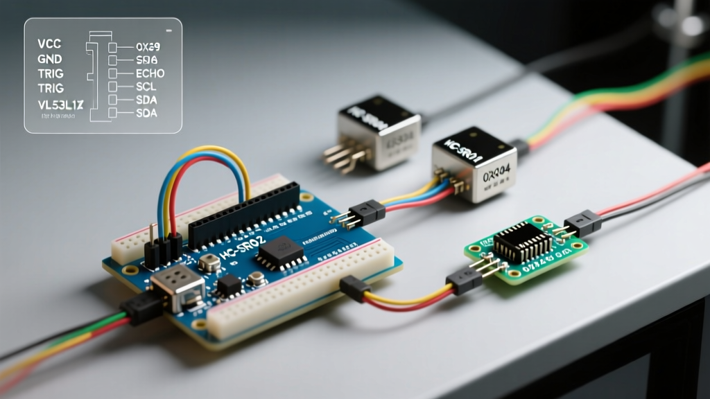
Every VL53L1X module powers on with the default I2C address 0x29. If you connect three of them to the same SDA/SCL lines, the Arduino cannot differentiate between them. The solution lies in the sensor's XSHUT (Shutdown) pin, which allows you to dynamically assign unique addresses during the setup() loop.
Dynamic Address Assignment via XSHUT Pins
To successfully initialize a 3-sensor VL53L1X array, you must wire the XSHUT pin of each sensor to a separate digital output on your Arduino. The initialization sequence must follow this exact logical order:
- Shutdown All: Set all XSHUT pins to
LOW. This forces all sensors into hardware standby, effectively removing them from the I2C bus. - Wake Sensor 1: Set Sensor 1 XSHUT to
HIGH. Wait 2ms for the sensor to boot. Because it is the only active sensor, it responds to0x29. - Readdress Sensor 1: Send the I2C command to change Sensor 1's address to
0x30. - Wake Sensor 2: Set Sensor 2 XSHUT to
HIGH. It boots on0x29. Change its address to0x31. - Wake Sensor 3: Set Sensor 3 XSHUT to
HIGH. Change its address to0x32.
For a comprehensive breakdown of the I2C register maps and timing diagrams required for this readdressing procedure, refer to the STMicroelectronics VL53L1X Datasheet. Furthermore, the hardware wiring specifics for breakout boards are excellently documented in the Adafruit VL53L1X Learning Guide and the Pololu VL53L1X Carrier Documentation.
Power Delivery and Ground Loop Mitigation
A frequently overlooked point of failure in multi-peripheral distance sensor Arduino setups is power rail sag. When three VL53L1X sensors fire their IR lasers simultaneously, or when an array of HC-SR04 transducers draw peak current during a ping, they create transient voltage drops on the 5V or 3.3V rails. If your Arduino is also driving an OLED display or a servo motor on the same rail, these transients will cause I2C bus resets or microcontroller brownouts.
Decoupling and Star Grounding
To stabilize your multi-sensor array, implement the following power conditioning rules:
- Local Decoupling: Solder a 100nF (0.1µF) ceramic capacitor directly across the VCC and GND pins of every single sensor module. This provides a local high-frequency charge reservoir.
- Bulk Capacitance: Place a 10µF to 47µF electrolytic capacitor at the main power entry point of your sensor array breadboard or custom PCB.
- Star Grounding: Do not daisy-chain the ground wires from sensor to sensor. Run a dedicated ground wire from each sensor's GND pin back to a single common ground point on the Arduino or power distribution board. This prevents ground loops and ensures the analog-to-digital converters (if using analog sensors) maintain a stable 0V reference.
Advanced Multi-Peripheral Integration: Pin Allocation Matrix
When combining a 3-node ToF distance array with a 0.96" SSD1306 OLED display and a PWM-driven steering servo, pin management becomes critical. Below is an optimized pin allocation matrix for the Arduino Nano Every, leveraging its separate I2C and serial hardware blocks.
| Peripheral | Interface | Nano Every Pins | Notes |
|---|---|---|---|
| ToF Sensor 1 (VL53L1X) | I2C + GPIO | A4 (SDA), A5 (SCL), D2 (XSHUT) | Address: 0x30 |
| ToF Sensor 2 (VL53L1X) | I2C + GPIO | A4 (SDA), A5 (SCL), D3 (XSHUT) | Address: 0x31 |
| ToF Sensor 3 (VL53L1X) | I2C + GPIO | A4 (SDA), A5 (SCL), D4 (XSHUT) | Address: 0x32 |
| SSD1306 OLED Display | I2C | A4 (SDA), A5 (SCL) | Address: 0x3C (Ensure 4.7kΩ pull-ups on SDA/SCL) |
| Steering Servo (MG996R) | PWM | D9 | Requires separate 6V BEC power supply |
Note on I2C Pull-ups: The internal pull-up resistors on the Arduino Nano Every are typically 20kΩ to 50kΩ, which is far too weak for a multi-device I2C bus running at 400kHz. You must solder external 4.7kΩ pull-up resistors between the SDA/SCL lines and the 3.3V/5V logic level to ensure clean signal edges and prevent phantom address collisions.
Troubleshooting Edge Cases in the Field
Even with perfect wiring and sequential code logic, environmental factors can degrade sensor performance. Understanding these edge cases separates amateur builds from professional-grade deployments.
Ultrasonic Acoustic Absorption
If your HC-SR04 or A02YYUW array is used for indoor mapping, be aware that soft materials like curtains, foam, and heavy clothing absorb 40kHz sound waves rather than reflecting them. If a sensor consistently returns timeout errors (maximum range) despite an object being physically present, the target material is likely acoustically transparent. In these scenarios, you must supplement the array with ToF or infrared sensors.
ToF Ambient IR Interference
The VL53L1X operates using a 940nm VCSEL (Vertical-Cavity Surface-Emitting Laser). While it features advanced ambient light rejection algorithms, pointing the sensor directly into incandescent bulbs, halogen lamps, or direct sunlight will flood the SPAD (Single-Photon Avalanche Diode) receiver array. This causes the sensor to report an artificially short distance or throw a PHASE_OUT_OF_RANGE error. If your 2026 robotics project operates outdoors, you must design physical shrouds or hoods for your ToF sensors to block direct solar ingress, or switch to 905nm pulsed LiDAR modules like the TFMini Plus ($39.00) which handle high-ambient-light environments significantly better.