
Beyond "Hello World": Deploying the LCD 1602 in the Field
Most online tutorials teaching how to use LCD 1602 display with Arduino stop at printing "Hello World" on a breadboard. But in 2026, if you are integrating a 16x2 character display into a real-world application—such as a greenhouse climate controller, a DIY brewing fermentation monitor, or an industrial tank level readout—breadboard jumper wires and default library settings will fail. Real-world environments introduce electromagnetic interference (EMI), voltage drops, and physical constraints that demand a more rigorous engineering approach.
The 1602 LCD, driven by the ubiquitous Hitachi HD44780 controller, remains a staple in embedded systems due to its low cost, high legibility in direct sunlight (when properly configured), and simple protocol. However, transitioning from a prototype to a field-deployable sensor node requires mastering I2C bus physics, power management, and environmental hardening. This guide provides the exact specifications, wiring topologies, and troubleshooting frameworks required to reliably interface an LCD 1602 with an Arduino for practical sensor applications.
Hardware Selection: Parallel vs. I2C Backpacks
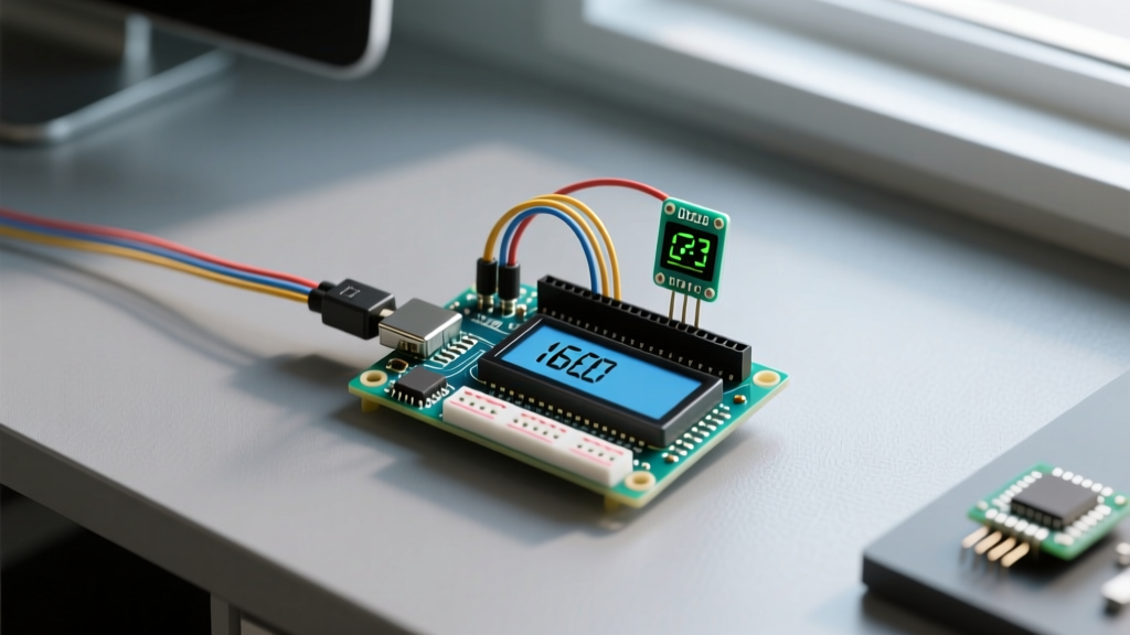
The standard 1602 LCD module requires 16 pins, with at least 6 digital I/O pins on your microcontroller dedicated to parallel data transfer. In modern sensor nodes where GPIO pins are at a premium (especially when integrating multiple I2C sensors like the BME280 or SCD41), using an I2C backpack is mandatory. The backpack utilizes a PCF8574 or MCP23008 I/O expander to convert the I2C serial protocol back into the parallel signals the HD44780 requires.
| Feature | Bare Parallel 1602 | PCF8574 I2C Backpack | DFRobot Gravity I2C (Premium) |
|---|---|---|---|
| GPIO Pins Required | 6 (Minimum) | 2 (SDA, SCL) | 2 (SDA, SCL) |
| Typical Cost (2026) | $3.50 - $5.00 | $4.50 - $6.50 | $11.00 - $14.00 |
| Wiring Complexity | High (16 pins) | Medium (4 pins + soldering) | Low (Plug-and-play JST) |
| Best Use Case | High-speed custom UI | Standard sensor readouts | Industrial/Enclosed builds |
The Physics of I2C: Wiring for Reliability
When learning how to use LCD 1602 display with Arduino for remote sensor nodes, cable length becomes a critical factor. The I2C bus was designed for on-board communication, not long-distance runs. According to Texas Instruments application notes on I2C bus capacitance, the maximum allowable bus capacitance is 400 pF. Every meter of standard ribbon cable adds roughly 50-100 pF of capacitance. If you mount your LCD 1602 on the door of an enclosure while the Arduino sits inside, a 2-meter cable run can easily exceed this limit, resulting in corrupted characters or a completely frozen display.
Actionable Wiring Rules for Field Deployments
- Use Twisted Pair Cables: Always route SDA and SCL lines using twisted pair wiring (like CAT5e Ethernet cable) to minimize crosstalk and EMI from nearby AC mains or stepper motors.
- Add Pull-Up Resistors: While the PCF8574 backpack has weak internal pull-ups, they are insufficient for cable runs over 30cm. Solder 4.7kΩ pull-up resistors between the SDA/SCL lines and the 5V VCC line at the Arduino end. If running at 400kHz Fast Mode, drop to 2.2kΩ resistors.
- Keep Lines Away from Noise: Never bundle I2C display cables in the same conduit or wire loom as relay switching lines or PWM motor control wires.
Addressing the I2C Address Trap
One of the most common failure points when integrating a 1602 display is an I2C address mismatch. The PCF8574 chip comes in two variants: the PCF8574 (default address 0x27) and the PCF8574A (default address 0x3F). Furthermore, cheap manufacturing batches sometimes alter the A0, A1, and A2 jumper pad configurations on the backpack PCB.
Pro-Tip: Never hardcode the I2C address in your production firmware without verifying it first. Use the standard Arduino I2C Scanner sketch (available in the official Arduino Wire library documentation) to ping the bus and confirm the exact hex address before compiling your sensor readout code.
Real-World Edge Cases and Troubleshooting
Even with perfect code, physical hardware quirks can derail a deployment. Here is how to handle the specific edge cases inherent to the 1602 LCD module.
1. The Contrast Potentiometer (V0) Blind Spot
Every 1602 module features a blue trimpot on the back of the PCB to adjust the V0 contrast voltage. Out of the box, this is often set to the extreme clockwise position, rendering the display completely blank. The Fix: Power the display and turn the potentiometer counter-clockwise slowly. You will first see a row of solid black blocks. Continue turning slightly past the blocks until the background clears but the characters remain sharp. For field deployments where temperature fluctuates, replace the mechanical trimpot with a fixed resistor network (typically a 1kΩ to 2kΩ resistor to ground) to prevent vibration from knocking the display out of focus.
2. The Backlight Jumper Override
If your application requires turning off the LCD backlight to save power during nighttime operation, you will use the lcd.setBacklight(LOW) command. However, on 90% of generic PCF8574 backpacks, there is a physical jumper on the top left corner that hardwires the backlight LED anode directly to VCC. If this jumper is present, software control is bypassed. The Fix: Desolder or snap off the jumper cap to allow the PCF8574's P7 pin to control the backlight via an onboard NPN transistor.
3. Ghosting and Character Corruption
If your sensor node switches a 12V water pump via a relay, the resulting inductive kickback can cause voltage sags on the 5V rail, leading to "ghosting" (random characters appearing) on the LCD. The Fix: Ensure your relay module has proper flyback diodes. Additionally, place a 100µF electrolytic capacitor and a 0.1µF ceramic decoupling capacitor directly across the VCC and GND pins on the back of the LCD 1602 PCB to stabilize the local power delivery during transient spikes.
Environmental Hardening and Power Management
When deploying an Arduino-based sensor readout outdoors or in harsh environments, the physical limitations of the LCD 1602 must be respected. Standard commercial HD44780 displays operate between 0°C and 50°C. If your greenhouse monitor drops below freezing, the liquid crystals will physically freeze, causing slow refresh rates or permanent damage. For sub-zero applications, you must source an "Industrial Grade" 1602 display rated for -20°C to 70°C, which typically costs around $12 to $18.
Furthermore, the standard yellow-green or blue LED backlight draws between 40mA and 80mA. If your sensor node is solar-powered or battery-operated, leaving the backlight on continuously will drain a 2000mAh 18650 cell in just over 24 hours. To mitigate this, wire the backlight control pin to a logic-level MOSFET (like the IRLZ44N) controlled by an Arduino digital pin, and implement a timeout function in your code that turns the display off after 30 seconds of inactivity, waking it only when a physical push-button is pressed or a critical sensor threshold is breached.
Creating Custom Sensor Icons
To maximize the 16x2 character grid, avoid wasting space on text like "Temp:" or "Hum:". Instead, utilize the HD44780's CGRAM (Character Generator RAM) to create custom 5x8 pixel icons. You can design a thermometer icon, a water droplet for humidity, or a leaf for CO2 levels. The Adafruit Character LCD guide provides excellent byte-array templates for these custom glyphs. By loading these into the first 8 memory slots of the display during the setup() loop, you can create a dense, highly readable dashboard that communicates critical environmental data at a single glance, proving that the humble 1602 LCD is still a powerhouse for real-world sensor applications in 2026.