
Introduction to IR Proximity Sensing
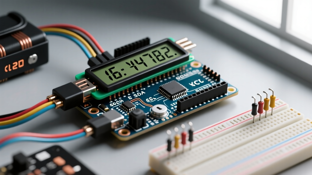
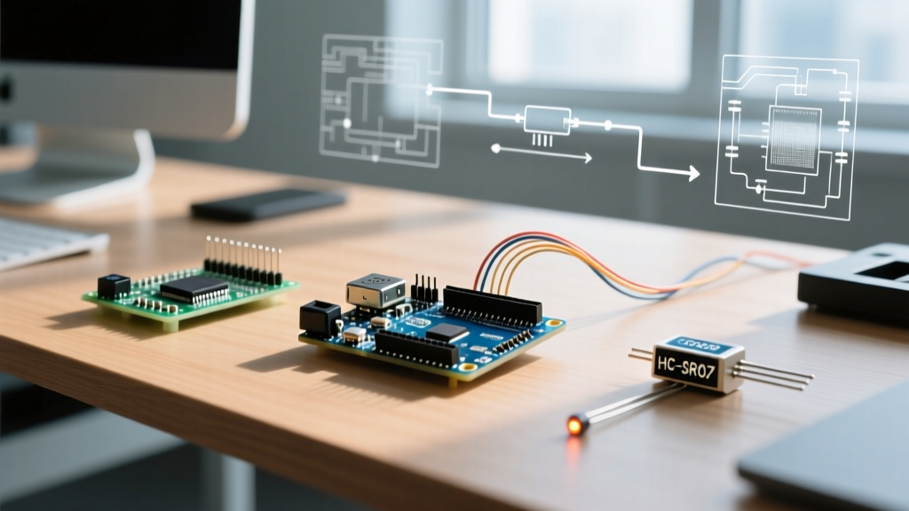
Interfacing an IR proximity sensor with Arduino is one of the most practical first steps for beginners entering the world of embedded systems. Whether you are building a line-following robot, an automated trash can, or a simple collision-avoidance rover, understanding how to detect physical objects without mechanical contact is essential. In this comprehensive 2026 guide, we will focus on the widely available HW-201 IR obstacle avoidance sensor, breaking down its internal electronics, wiring protocols, and the real-world environmental edge cases that trip up most beginners.
How the HW-201 Module Actually Works
Before writing any code, it is critical to understand the physics and electronics governing your sensor. The HW-201 module does not measure exact distance like an ultrasonic sensor; instead, it detects the presence of an object within a configurable threshold using diffuse reflectance.
The Physics: 940nm Infrared Light
The module features two distinct LEDs. One is a clear or slightly tinted 940nm infrared emitting diode, which constantly blasts invisible IR light forward. The second is a black photodiode, which acts as a receiver. When an object enters the sensor's field of view, the 940nm light bounces off the object's surface and back into the photodiode. The more reflective the surface, the more light returns.
The Electronics: LM393 Comparator
The raw analog signal from the photodiode is too noisy and weak for a microcontroller to read reliably. This is where the Texas Instruments LM393 dual differential comparator comes in. The LM393 compares the voltage from the photodiode against a reference voltage set by the onboard blue trimpot (potentiometer). If the received IR light exceeds the threshold, the LM393's open-collector output pulls the digital signal pin LOW.
Expert Insight: The LM393 features an open-collector output. This means it can only pull the signal line to ground (LOW). It cannot drive it HIGH. The HW-201 module includes a 10kΩ pull-up resistor to VCC to ensure the line returns to HIGH when no object is detected. If you ever design a custom PCB, do not forget this pull-up resistor!
Bill of Materials (2026 Pricing & Availability)
To follow this tutorial, you will need a few basic components. Prices reflect standard hobbyist market rates as of early 2026.
| Component | Specific Model | Est. Price | Notes |
|---|---|---|---|
| Microcontroller | Arduino Uno R4 Minima | $22.00 | Modern 32-bit ARM Cortex-M4; fully backward compatible with R3 code. |
| IR Sensor Module | HW-201 (4-Pin) | $1.80 | Ensure you get the 4-pin version (VCC, GND, DO, AO) for analog capabilities. |
| Jumper Wires | 22 AWG Dupont M-F | $4.50 | Female-to-Male for breadboard prototyping. |
| Decoupling Capacitor | 100nF Ceramic (0.1µF) | $0.10 | Highly recommended for long wire runs to prevent VCC ripple. |
Step-by-Step Wiring Guide
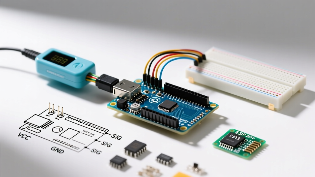
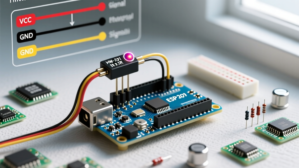
Wiring the IR proximity sensor with Arduino is straightforward, but proper power delivery is often overlooked. The HW-201 operates optimally between 3.3V and 5V. We will use the 5V rail on the Arduino Uno R4.
- Power (VCC): Connect the module's VCC pin to the Arduino's
5Vpin. Do not use the 3.3V pin, as the IR LED forward voltage requires closer to 5V for maximum range. - Ground (GND): Connect the module's GND pin to any of the Arduino's
GNDpins. - Digital Out (DO): Connect the DO pin to Arduino Digital Pin
2. This pin outputs a clean HIGH/LOW signal based on the trimpot threshold. - Analog Out (AO): Connect the AO pin to Arduino Analog Pin
A0. This provides the raw, un-thresholded voltage from the photodiode receiver.
Hardware Tip: If your sensor is mounted more than 15cm away from the Arduino, solder a 100nF ceramic capacitor directly across the VCC and GND pins on the back of the HW-201 module. This filters out high-frequency noise induced by long wires.
Arduino Code: Digital and Analog Interfacing
Below is a robust, beginner-friendly sketch that reads both the digital threshold state and the raw analog reflectance value. We utilize the Arduino DigitalReadSerial and AnalogInOutSerial paradigms, combined into a single loop with a non-blocking delay.
// Pin Definitions
const int DIGITAL_PIN = 2;
const int ANALOG_PIN = A0;

// Timing variables for non-blocking delay
unsigned long lastPrintTime = 0;
const long printInterval = 250; // Print every 250ms

void setup() {
  Serial.begin(115200);
  pinMode(DIGITAL_PIN, INPUT);
  // No need to set analog pin mode explicitly
}

void loop() {
  // Read sensor states
  int digitalState = digitalRead(DIGITAL_PIN);
  int analogValue = analogRead(ANALOG_PIN);

  // Non-blocking serial output
  unsigned long currentTime = millis();
  if (currentTime - lastPrintTime >= printInterval) {
    lastPrintTime = currentTime;

    Serial.print("Obstacle Detected (Digital): ");
    Serial.print(digitalState == LOW ? "YES" : "NO");

    Serial.print(" | Raw Reflectance (Analog): ");
    Serial.println(analogValue);
  }
}
Understanding the Code Output
When you open the Serial Monitor at 115200 baud, you will see two data points. The Digital read will flip to YES (LOW) when an object crosses the physical threshold set by the potentiometer. The Analog read will output a value between 0 and 1023. Note: On the HW-201, a HIGHER analog value means MORE IR light is being received (object is closer or more reflective).
Calibration: Tuning the Potentiometer
The blue trimpot on the HW-201 module dictates the sensitivity of the digital output. Out of the box, these modules are rarely calibrated for your specific project needs.
- Clockwise Rotation: Increases the reference voltage threshold. The sensor becomes less sensitive, requiring an object to be much closer (or highly reflective) to trigger the digital pin LOW.
- Counter-Clockwise Rotation: Decreases the threshold. The sensor becomes more sensitive, triggering from further away but risking false positives from ambient IR noise.
Calibration Procedure: Place your target object at the exact distance you want the trigger to occur. Slowly turn the trimpot with a small Phillips screwdriver until the digital output LED on the module (usually labeled D0-LED) flickers right on the edge of activating. Lock it in by adding a tiny dab of hot glue or clear nail polish to the screw to prevent mechanical vibration from shifting it during robot operation.
Real-World Edge Cases & Environmental Interference
Tutorials often assume ideal laboratory conditions. In the real world, IR proximity sensors face severe environmental challenges. Understanding these will separate a novice from an expert.
1. The Sunlight Saturation Problem
The sun is a massive emitter of broadband electromagnetic radiation, including heavy output in the 940nm IR spectrum. If your Arduino project is deployed outdoors or near a sunlit window, the ambient IR will completely saturate the photodiode. The sensor will act as if an object is constantly pressed against it. The Fix: You must build a physical shroud (using heat-shrink tubing or 3D printed PLA) around the photodiode to block off-axis sunlight, or switch to a modulated IR sensor (like the TSOP382) which looks for a specific 38kHz pulse frequency rather than raw light intensity.
2. Surface Reflectivity and Color
IR sensors rely on diffuse reflection. A white piece of paper will reflect up to 90% of 940nm light, triggering the sensor from 15cm away. Conversely, matte black electrical tape or dark fabrics can absorb up to 95% of that same light. If your robot is navigating a dark room with black baseboards, the sensor may fail to detect the wall entirely until physical contact is made. The Fix: If detecting dark objects is required, IR proximity is the wrong tool. Upgrade to a Time-of-Flight (ToF) sensor like the VL53L0X, which relies on laser photon timing rather than surface reflectance.
Troubleshooting Matrix
Use this diagnostic table if your IR proximity sensor with Arduino is misbehaving.
| Symptom | Probable Cause | Technical Fix |
|---|---|---|
| Digital pin is always LOW (Object Detected) | Ambient IR saturation or trimpot fully CCW. | Shield from sunlight; adjust trimpot clockwise. |
| Digital pin is always HIGH (No Detection) | IR LED is blown or trimpot fully CW. | Verify IR LED glow via smartphone camera; adjust trimpot CCW. |
| Analog value stuck at 0 or 1023 | Wiring fault or LM393 rail-to-rail saturation. | Check AO jumper wire; ensure VCC is stable at 5V. |
| Erratic digital triggering (flickering) | VCC power supply ripple or loose Dupont connection. | Add 100nF decoupling cap; replace jumper wires. |
Final Thoughts for Makers
Mastering the HW-201 IR proximity sensor with Arduino provides a foundational understanding of analog-to-digital conversion, comparator circuits, and optical physics. While it lacks the millimeter precision of LiDAR or ToF sensors, its sub-$2 price point and simple digital interface make it an unbeatable choice for basic collision avoidance, liquid level detection, and tachometry in 2026 DIY projects. Always remember to account for ambient light and surface colors in your mechanical design, and your sensor integration will be rock solid.