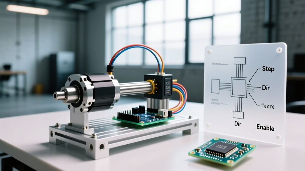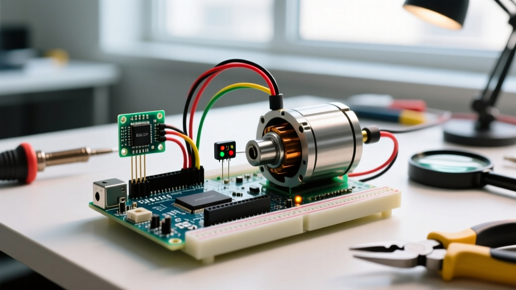

Why Sensor Integration Transforms Stepper Motor Control
Open-loop stepper motors are inherently blind. When you command an Arduino to move a NEMA 17 stepper 10,000 steps, the microcontroller assumes the physical rotor has followed suit. However, mechanical binding, sudden load spikes, or aggressive acceleration curves can cause missed steps, resulting in cumulative positional drift. By integrating a positional sensor into your arduino stepper motor with driver ecosystem, you transition from a blind open-loop system to a homed, pseudo-closed-loop architecture. This tutorial details how to integrate an A3144 Hall effect sensor with an A4988 driver and a NEMA 17 stepper to achieve repeatable, sub-millimeter homing accuracy for CNC, 3D printing, and automated dispensing applications in 2026.
Hardware Selection for 2026 Builds
Component selection dictates the thermal and kinematic ceiling of your build. While generic clone boards flood the market, relying on them for continuous duty cycles often leads to thermal throttling. Here is the exact bill of materials (BOM) we recommend for a robust sensor-integrated setup:
- Stepper Motor: NEMA 17 (Model 17HS4401S). Rated at 1.5A per phase with a holding torque of 40 N·cm. Retail price: $12–$15.
- Driver Module: Genuine Pololu A4988 Stepper Motor Driver Carrier ($6.50). Avoid unbranded $1.20 clones; their sense resistors often drift under thermal load, altering current limits.
- Homing Sensor: A3144EUA Hall Effect Switch ($1.50). Unlike mechanical microswitches (e.g., Omron D2F), Hall sensors offer zero mechanical bounce and infinite lifecycle actuation.
- Power Supply: 24V 5A Switching PSU ($18). While 12V works, 24V drastically improves the current rise time (L/R time constant) in the motor coils, enabling higher RPMs before torque drops off.
Power Delivery and Decoupling: The Overlooked Step
Before wiring the logic pins, you must stabilize the motor power rail. Stepper motors generate massive inductive kickback when coils are energized and de-energized. Without local energy storage, these voltage spikes will exceed the A4988's 35V absolute maximum rating, instantly destroying the driver IC.
Actionable Specifics: Solder a 100µF, 35V low-ESR electrolytic capacitor directly across the VMOT and GND pins on the A4988 carrier board. Keep the lead length under 5mm. This local decoupling absorbs high-frequency transients that your main power supply's bulk capacitors cannot react to fast enough.
Wiring the Arduino Stepper Motor with Driver and Sensor
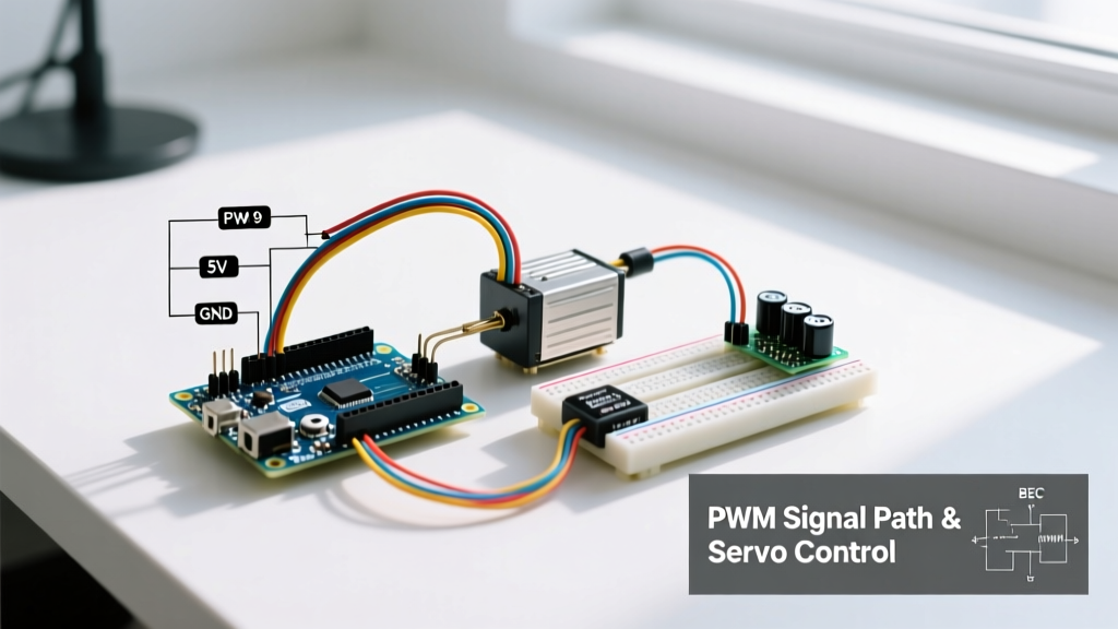
Proper wiring separates functional prototypes from reliable machines. Below is the exact pinout mapping for an Arduino Uno (ATmega328P) interfacing with the A4988 and A3144 sensor.
Logic and Control Pinout
| A4988 Pin | Arduino Pin | Function & Notes |
|---|---|---|
| STEP | Pin 3 | Receives pulse train (must be PWM capable or use AccelStepper) |
| DIR | Pin 4 | HIGH = Clockwise, LOW = Counter-Clockwise |
| ENABLE | Pin 5 | Active LOW. Pull to GND to enable, HIGH to sleep/coast |
| MS1, MS2, MS3 | Pins 6, 7, 8 | Microstepping configuration (see table below) |
Sensor Integration Pinout
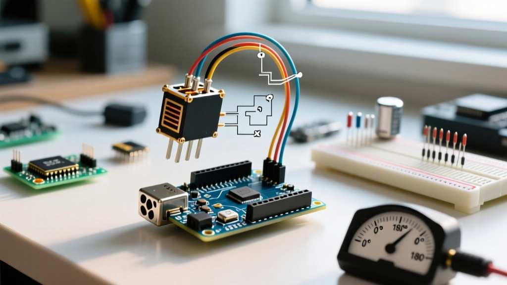
The A3144 Hall effect sensor operates as an open-drain NPN transistor. When a magnetic field (south pole) exceeds the B(op) threshold (typically 30 Gauss), it pulls the output pin to ground.
- VCC: Arduino 5V
- GND: Arduino GND
- OUT: Arduino Pin 2 (Hardware Interrupt 0)
Critical Expert Note: Do not rely solely on the Arduino's internal 20kΩ pull-up resistor for the sensor line. In environments with stepper motor EMI, high-impedance lines act as antennas, causing false triggers. Solder an external 4.7kΩ pull-up resistor between the 5V line and the sensor's OUT pin. For runs longer than 30cm, use a twisted-pair cable for the sensor wiring to reject common-mode noise.
Setting the VREF Current Limit
The most common cause of skipped steps and melted driver boards is an improperly set VREF. The A4988 uses a sense resistor (Rs) to calculate the current limit. On genuine Pololu boards, Rs = 0.05Ω.
The VREF Formula: VREF = I_max × 8 × Rs
For our 1.5A NEMA 17: VREF = 1.5 × 8 × 0.05 = 0.60V
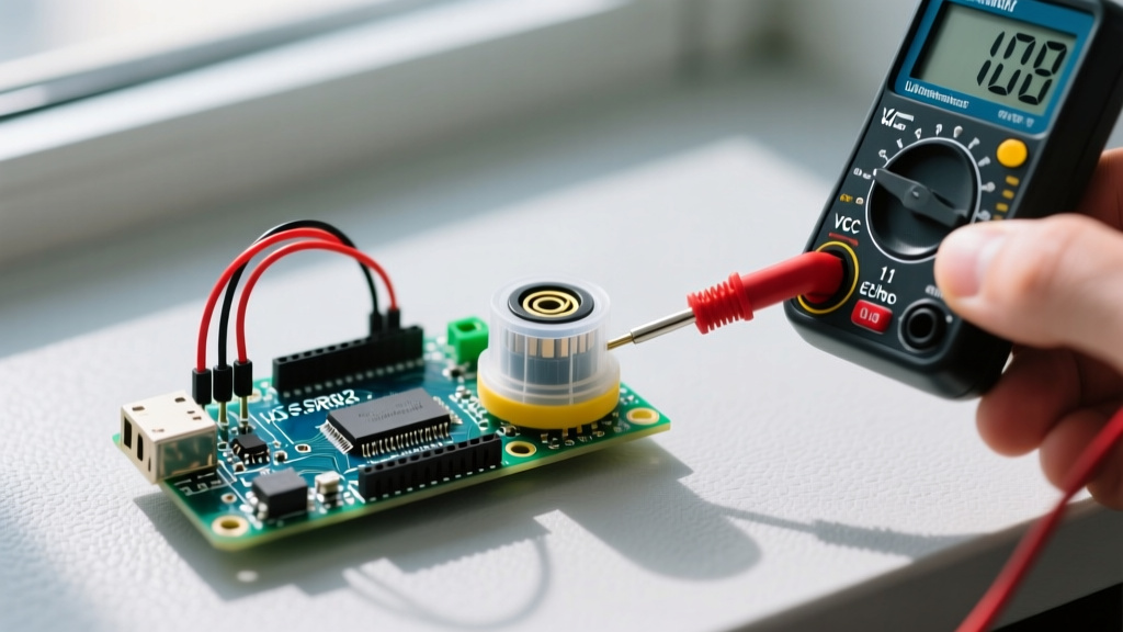
Power the A4988 logic (VDD) with 5V, but leave VMOT disconnected. Place your multimeter's positive probe on the VREF test point and the negative probe on GND. Turn the brass potentiometer with a ceramic screwdriver until you read exactly 0.60V. If you are running the motor without active cooling (heatsink + fan), derate the current to 1.2A (VREF = 0.48V) to prevent the driver's internal thermal shutdown at 165°C.
Microstepping Truth Table
Full-stepping a NEMA 17 at low speeds introduces severe mid-band resonance, often causing the motor to stall around 200–300 RPM. Microstepping smooths the current sine wave, reducing acoustic noise and resonance. Configure your MS pins accordingly:
| Resolution | MS1 | MS2 | MS3 | Steps per Revolution (1.8° Motor) |
|---|---|---|---|---|
| Full Step | LOW | LOW | LOW | 200 |
| 1/2 Step | HIGH | LOW | LOW | 400 |
| 1/4 Step | LOW | HIGH | LOW | 800 |
| 1/8 Step | HIGH | HIGH | LOW | 1600 |
| 1/16 Step | HIGH | HIGH | HIGH | 3200 |
Programming the Sensor-Triggered Homing Routine
To manage acceleration profiles and non-blocking step generation, we utilize Mike McCauley's AccelStepper library. The goal of the homing routine is to find the sensor, back off to remove mechanical hysteresis, and establish a precise 'zero' coordinate.
The Homing Algorithm Logic
- Fast Approach: Move the carriage toward the sensor at a moderate speed (e.g., 1000 steps/sec) until the hardware interrupt triggers.
- Debounce & Back-off: Stop immediately. Move away from the sensor by 400 steps at a slow speed (200 steps/sec) to clear the magnetic hysteresis zone.
- Precision Crawl: Creep back toward the sensor at 50 steps/sec until the exact edge is detected again.
- Zeroing: Call
stepper.setCurrentPosition(0). Your coordinate system is now locked to a physical datum.
Using hardware interrupts via attachInterrupt() is mandatory here. Polling the sensor pin inside the main loop while generating step pulses will result in missed sensor triggers, causing the carriage to crash into the hard stop. Set the interrupt mode to FALLING to catch the exact moment the Hall sensor pulls the line low.
Troubleshooting Common Failure Modes
Even with perfect wiring, electromechanical systems present edge cases. Here is how to diagnose the three most frequent issues in sensor-integrated stepper setups:
1. False Homing Triggers Mid-Travel
Symptom: The motor stops and resets its zero position randomly during a print or cut.
Root Cause: Electromagnetic interference (EMI) from the stepper coils coupling into the high-impedance sensor wire.
Fix: Ensure the 4.7kΩ external pull-up resistor is installed. Route the sensor cables at a 90-degree angle to the motor phase wires. If the issue persists, add a 100nF ceramic capacitor between the sensor OUT pin and GND to create a low-pass hardware filter.
2. Motor Stalls and Whines at High Speed
Symptom: The motor vibrates loudly and fails to reach the target position above 600 RPM.
Root Cause: Coil inductance prevents current from reaching the 1.5A target before the A4988 switches to the next step phase. Torque collapses.
Fix: Upgrade your power supply from 12V to 24V. The higher voltage forces current through the inductive coils faster, flattening the torque curve up to 1500 RPM.
3. Inconsistent Homing Repeatability (>0.5mm variance)
Symptom: The carriage stops in a slightly different physical location every time it homes.
Root Cause: Approaching the sensor too quickly, combined with the A3144's magnetic hysteresis (the gap between B(op) and B(rp)).
Fix: Implement the 'back-off and crawl' algorithm detailed in the homing logic section. The final approach must be done at 1/16th microstepping at a crawl speed to guarantee sub-0.1mm repeatability.
Final Thoughts on System Reliability
Integrating sensors with an arduino stepper motor with driver elevates your project from a hobbyist experiment to a reliable automation tool. By respecting the physics of inductive loads, calculating VREF accurately, and utilizing hardware interrupts for homing, you eliminate the positional drift that plagues basic open-loop designs. As you scale this architecture for multi-axis CNC or precision fluid dispensing, remember that mechanical rigidity and cable management are just as critical as the code you write.