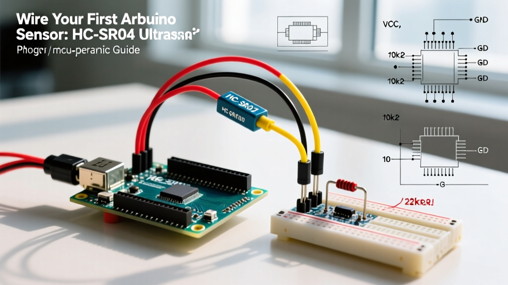

The Ultimate Starting Point for Arduino Sensor Integration
Entering the world of microcontroller peripherals can be overwhelming, but mastering your first arduino sensor is a rite of passage that unlocks endless DIY possibilities. While there are hundreds of modules on the market, the HC-SR04 Ultrasonic Distance Sensor remains the undisputed champion for beginners. It teaches fundamental concepts: time-of-flight physics, GPIO timing, signal conditioning, and non-blocking code architecture.
In this 2026 guide, we will move past the superficial "copy-paste" tutorials. We will dissect the exact hardware wiring required to prevent frying modern 3.3V microcontrollers, analyze the hidden flaws in standard Arduino timing functions, and implement temperature-compensated distance calculations used in professional robotics.
Anatomy and Specifications of the HC-SR04
The HC-SR04 operates on a simple sonar principle. It emits an eight-cycle 40 kHz ultrasonic burst and listens for the echo. By measuring the time delta between the trigger pulse and the echo return, the microcontroller calculates the distance. Before wiring, you must understand the hard electrical limits of the module.
| Parameter | Specification | Real-World Notes (2026) |
|---|---|---|
| Operating Voltage | 5V DC | Tolerates 4.5V to 5.5V. Below 4.5V, the onboard MAX232 equivalent chip fails to drive the transducers. |
| Working Current | 15 mA (Active) | Quiescent current is ~2 mA. Do not power directly from a 3.3V LDO without checking current limits. |
| Measuring Range | 2 cm to 400 cm | Accuracy degrades past 300 cm due to acoustic beam divergence (15° cone angle). |
| Trigger Pulse | 10 μs TTL | Requires a clean, debounced 5V or 3.3V HIGH signal. |
| Average Cost | $1.50 - $2.80 USD | Generic clones are ubiquitous. For industrial environments, upgrade to the MaxBotix LV-MaxSonar (~$30). |
Hardware Wiring: The 3.3V Logic Trap
The most common mistake beginners make when interfacing an arduino sensor with modern boards is ignoring logic level shifting. The HC-SR04 is a 5V device. Its ECHO pin outputs a 5V HIGH signal when returning the pulse width.
If you are using a classic 5V Arduino Uno R3, you can wire the ECHO pin directly to a digital input. However, if you are using an Arduino Nano ESP32, Teensy 4.1, or any 3.3V logic board, feeding 5V into the GPIO pin will degrade the silicon over time, eventually destroying the microcontroller's input buffer.
Designing a Passive Voltage Divider
To safely step down the 5V ECHO signal to a 3.3V-safe level, use a simple resistor voltage divider. The formula is:
V_out = V_in × (R2 / (R1 + R2))
Using standard E12 resistor values:
- R1 (Series Resistor): 2 kΩ (Connect between HC-SR04 ECHO and MCU GPIO)
- R2 (Pull-down Resistor): 3.3 kΩ (Connect between MCU GPIO and GND)
Calculation: 5V × (3.3 / (2 + 3.3)) = 3.11V. This is perfectly safe for 3.3V logic and provides a fast enough RC time constant for the microsecond-level pulses used by the sensor.
Software Architecture: Why pulseIn() is a Trap
Most beginner tutorials rely on the native Arduino pulseIn() function. While easy to write, pulseIn() is a blocking function. It halts the entire microcontroller, waiting for the echo pin to go HIGH and then LOW. If the sensor is pointed at an open window or sound-absorbing foam, the echo never returns, and your code freezes for up to 3 seconds (the default timeout).
In a real-world project where your arduino sensor must run alongside motor control or Wi-Fi communication, blocking code is unacceptable.
The Solution: Timer-Based Interrupts with NewPing
Professional firmware utilizes hardware timers to measure pulse widths in the background. The NewPing library leverages pin-change interrupts and hardware timers to measure the echo without blocking the main loop(). It also includes built-in median filtering to discard acoustic anomalies.
#include <NewPing.h>

#define TRIGGER_PIN  9
#define ECHO_PIN     10
#define MAX_DISTANCE 400 // Max range in cm

// Initialize the sensor object
NewPing sonar(TRIGGER_PIN, ECHO_PIN, MAX_DISTANCE);

void setup() {
  Serial.begin(115200);
  // Allow serial buffer to initialize on modern USB-C MCU boards
  delay(1500);
}

void loop() {
  // ping_cm() handles the timer, trigger, and echo calculation
  unsigned int distance = sonar.ping_cm();

  if (distance == 0) {
    Serial.println("Out of range or acoustic timeout.");
  } else {
    Serial.print("Distance: ");
    Serial.print(distance);
    Serial.println(" cm");
  }

  // Non-blocking delay using millis() is recommended for complex loops
  delay(50); // Wait 50ms between pings (max 20Hz polling rate)
}
Advanced Calibration: Temperature Drift and Edge Cases
To elevate your project from a hobbyist toy to a reliable instrument, you must account for environmental physics. The HC-SR04 calculates distance assuming the speed of sound is exactly 343 meters per second. However, this is only true at 20°C (68°F).
Expert Insight: According to thermodynamic principles outlined by the Engineering Toolbox, the speed of sound in dry air increases by approximately 0.606 m/s for every 1°C rise in temperature. If your arduino sensor operates in an unheated garage at 0°C, the speed of sound drops to 331.3 m/s. This introduces a 3.5% measurement error, meaning a 100 cm distance will read as 103.5 cm.
Implementing Software Compensation
If your project requires high precision, pair your HC-SR04 with a digital temperature sensor (like the BME280) and apply the compensation formula in your C++ code:
speed_of_sound = 331.3 + (0.606 * temperature_celsius);
By dynamically adjusting the divisor in your time-of-flight calculation, you eliminate seasonal and environmental drift.
Real-World Failure Modes and Troubleshooting
Even with perfect wiring and non-blocking code, ultrasonic sensors exhibit specific failure modes in the field. Keep this troubleshooting matrix handy:
- Phantom Readings (Shorter than reality): Caused by acoustic crosstalk if you have multiple HC-SR04 modules firing simultaneously. Fix: Stagger the trigger pulses by at least 60ms per sensor.
- Zero / Timeout Readings: Occurs when the target surface is highly absorbent (e.g., thick curtains, acoustic foam) or angled more than 20° away from the sensor, deflecting the 40 kHz wave away from the receiver.
- Jittery / Noisy Data: Often caused by 5V rail ripple from cheap USB power supplies or inductive kickback from nearby DC motors. Fix: Add a 100 μF electrolytic capacitor across the sensor's VCC and GND pins to stabilize the local power envelope during the high-current transmit burst.
Next Steps in Your Sensor Journey
Mastering the HC-SR04 arduino sensor provides the foundational knowledge required for more complex peripherals. The timing concepts you learned here translate directly to interfacing with LiDAR modules, time-of-flight (ToF) infrared sensors like the VL53L0X, and even automotive radar protocols. Move forward by integrating this sensor into a closed-loop PID control system for a self-balancing robot or an automated collision-avoidance rover.