
Non-Invasive AC Current Sensing: The 2026 Standard
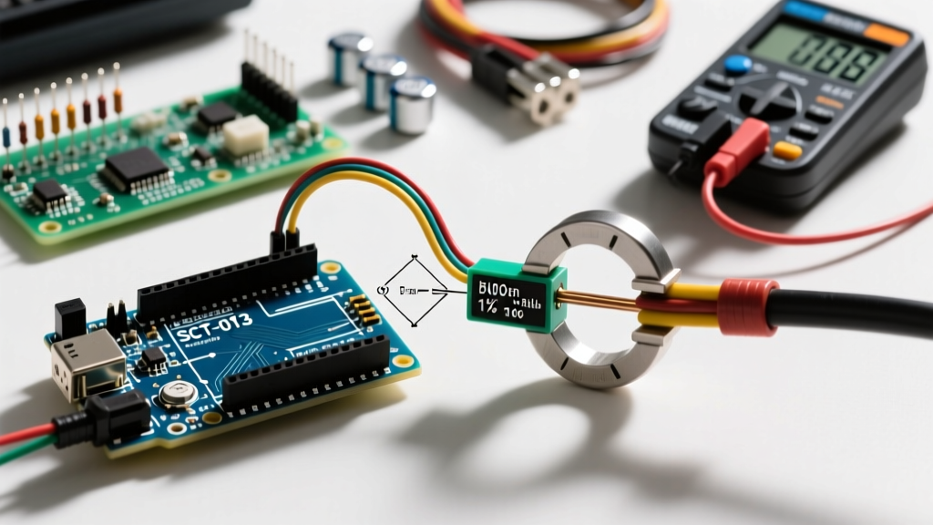
As smart home energy monitoring and DIY solar grid-tie projects continue to surge in 2026, accurately measuring alternating current without severing mains wiring is a critical skill. The Arduino AC current sensor workflow almost universally relies on the YHDC SCT-013 split-core current transformer (CT). Priced between $8 and $14 for genuine units, it offers a safe, non-invasive method to monitor loads ranging from a single 60W router to a 50A EV charger circuit.
However, simply plugging a CT sensor into an Arduino analog pin will not yield usable data—and can destroy your microcontroller. This guide provides the exact wiring schematics, burden resistor mathematics, and EmonLib calibration code required to build a production-grade AC current monitor.
⚠️ HIGH VOLTAGE WARNING: While the SCT-013 clamps around the outside of an insulated wire, you must still route wires through the sensor core. Never work inside an open mains breaker panel unless you are a qualified electrician. Always turn off the main breaker before routing conductors through the CT window.
Hardware Deep Dive: Choosing the Right SCT-013 Variant
The most common failure mode for beginners is purchasing the wrong SCT-013 variant. The manufacturer produces several models that look identical but output entirely different signals. In 2026, the market is flooded with clones; always verify the exact part number printed on the label.
| Model Number | Max Primary Current | Output Type | Internal Burden? | Best Use Case |
|---|---|---|---|---|
| SCT-013-000 | 100A | 0-50mA (Current) | No (Requires External) | Custom Arduino/ESP32 circuits, high precision |
| SCT-013-030 | 30A | 0-1V AC (Voltage) | Yes (62Ω) | Direct plug-and-play with 3.3V/5V ADCs |
| SCT-013-050 | 50A | 0-1V AC (Voltage) | Yes (45Ω) | Heavy appliance monitoring (Dryers, Ovens) |
This guide focuses on the SCT-013-000 (100A), as it requires external burden resistor calculation and biasing, representing the most complex and educational wiring scenario for an Arduino AC current sensor setup.
The Mathematics: Calculating the Burden Resistor
The SCT-013-000 has 2000 internal turns. If 100A flows through the primary wire, the secondary coil outputs 50mA (100A / 2000). Because the Arduino analog-to-digital converter (ADC) measures voltage, not current, we must pass this secondary current through a "burden resistor" to generate a proportional AC voltage.
Step 1: Determine Maximum Peak Secondary Current
AC current is measured in RMS (Root Mean Square). To prevent the Arduino ADC from clipping the waveform, we must calculate the peak current.
- Primary Peak Current: 100A × √2 = 141.4A
- Secondary Peak Current: 141.4A / 2000 turns = 0.0707A
Step 2: Calculate Ideal Burden Resistance
The Arduino Uno (ATmega328P) uses a 5V reference, meaning the ADC reads 0V to 5V. Because we are measuring AC, the waveform swings positive and negative. We must bias the signal to 2.5V (half of Vcc). Therefore, the maximum allowable peak voltage swing is 2.5V.
- Ideal Resistance: 2.5V / 0.0707A = 35.3Ω
Since 35.3Ω is not a standard resistor value, we select the next closest standard value lower than the ideal to ensure the waveform never clips. A 33Ω resistor is the optimal choice for a 5V Arduino. If you are using a 3.3V microcontroller (like the ESP32 or Arduino Due), the bias point is 1.65V, requiring a 22Ω burden resistor.
Step-by-Step Wiring Guide
To interface the SCT-013-000 with an Arduino, you need to create a voltage divider to bias the AC signal, and add a capacitor to stabilize the reference voltage. According to the OpenEnergyMonitor CT Sensor Interfacing Guide, this analog conditioning is non-negotiable for accurate RMS sampling.
Component List
- 1x YHDC SCT-013-000 Current Transformer
- 1x 33Ω Burden Resistor (1/4W or 1/2W metal film)
- 2x 10kΩ Resistors (for voltage divider)
- 1x 10µF Electrolytic Capacitor (or 100nF ceramic)
- 1x 1kΩ Protection Resistor (optional, limits current into the ADC pin)
Wiring Connections
- Voltage Divider: Connect the two 10kΩ resistors in series between the Arduino 5V pin and GND. The junction between them creates a 2.5V virtual ground.
- Capacitor: Connect the 10µF capacitor between the 2.5V junction and GND to filter high-frequency noise.
- Burden Resistor: Connect the 33Ω resistor directly across the two wires of the SCT-013 audio jack.
- Signal Routing: Connect one wire of the SCT-013 to the 2.5V virtual ground junction.
- ADC Input: Connect the other wire of the SCT-013 to Arduino Analog Pin A0. (Place the 1kΩ protection resistor in series here if desired).
Arduino Code: EmonLib Implementation
Calculating true RMS current from raw ADC samples requires precise timing and square-root math. Rather than writing this from scratch, the industry standard is the EmonLib library. You can install it via the Arduino Library Manager by searching for "EmonLib".
#include <EmonLib.h>

EnergyMonitor emon1;

// Calibration constant (explained below)
const float I_CAL = 111.1;

void setup() {
  Serial.begin(115200);
  // Initialize CT sensor: Analog Pin, Calibration Constant
  emon1.current(A0, I_CAL);
}

void loop() {
  // Calculate Irms over 1480 milliseconds (approx 60 cycles at 50Hz/60Hz)
  double Irms = emon1.calcIrms(1480);

  // Filter out ghost voltage / ADC noise when no load is present
  if (Irms < 0.15) {
    Irms = 0.0;
  }

  Serial.print("Current: ");
  Serial.print(Irms);
  Serial.println(" A");

  delay(1000);
}
Calibrating the I_CAL Constant
The I_CAL value translates the ADC voltage back into primary Amps. The theoretical formula is:
I_CAL = (CT Turns Ratio / Burden Resistor) * (ADC Vref / 1024)
For our setup: (2000 / 33) * (5.0 / 1024) = 0.297. Wait, EmonLib expects the ratio of primary current to ADC voltage. The correct theoretical EmonLib constant is roughly 111.1 for a 100A CT with a 33Ω burden on a 5V system.
Real-World Calibration: Component tolerances (especially the 33Ω resistor and the Arduino's internal 5V regulator) mean theoretical math is rarely perfect. To calibrate:
- Plug in a known resistive load (e.g., a 1000W space heater or a 100W incandescent bulb).
- Measure the actual current using a high-quality True-RMS digital multimeter (like a Fluke 87V).
- Adjust the
I_CALvalue in your code up or down until the Serial Monitor matches your multimeter reading.
Troubleshooting Edge Cases & Signal Noise
When building an Arduino AC current sensor circuit, analog noise is the primary adversary. As detailed in Analog Devices' application notes on CT measurements, improper grounding and sampling rates can introduce severe errors.
1. "Ghost" Readings at Zero Load
Symptom: The serial monitor reads 0.2A to 0.5A even when the monitored appliance is unplugged.
Cause: The Arduino 10-bit ADC is highly sensitive to electromagnetic interference (EMI) and floating ground potentials. The 2.5V bias point is picking up ambient 50/60Hz noise.
Fix: Implement a software threshold (as shown in the code above: if (Irms < 0.15) Irms = 0.0;). For a hardware fix, ensure your 10µF bias capacitor is placed as physically close to the Arduino GND and A0 pins as possible.
2. Waveform Clipping (Maxing out at ~70A)
Symptom: Current readings cap out prematurely, or the calculated power seems disproportionately low for high loads.
Cause: Your burden resistor is too high, causing the peak AC voltage to exceed the 2.5V bias swing, hitting the 0V or 5V ADC rails.
Fix: Drop the burden resistor from 33Ω to 22Ω and recalibrate the I_CAL constant.
3. 50Hz vs 60Hz Grid Sampling Errors
Symptom: Readings fluctuate wildly from second to second.
Cause: The calcIrms(1480) function samples for a fixed number of milliseconds. If your grid frequency drifts, or if you move a 60Hz-coded project to a 50Hz country (like the UK or Australia), the sampling window won't capture full sine wave cycles, resulting in DC offset errors.
Fix: For production-grade 2026 deployments, integrate a Zero-Crossing Detector (ZCD) circuit using an optocoupler (like the H11AA1) to trigger ADC sampling precisely at the start of each AC cycle, rather than relying on arbitrary millisecond delays.
Final Thoughts on System Integration
Integrating an Arduino AC current sensor using the SCT-013-000 provides a robust foundation for home energy dashboards, automated load shedding, and solar diversion controllers. By respecting the analog conditioning requirements—specifically the burden resistor sizing and DC bias network—you bypass the most common pitfalls of DIY energy monitoring. Always prioritize True-RMS calibration against a known load, and consider upgrading to a 12-bit ADC microcontroller like the ESP32 if your project requires sub-amp precision for standby power monitoring.