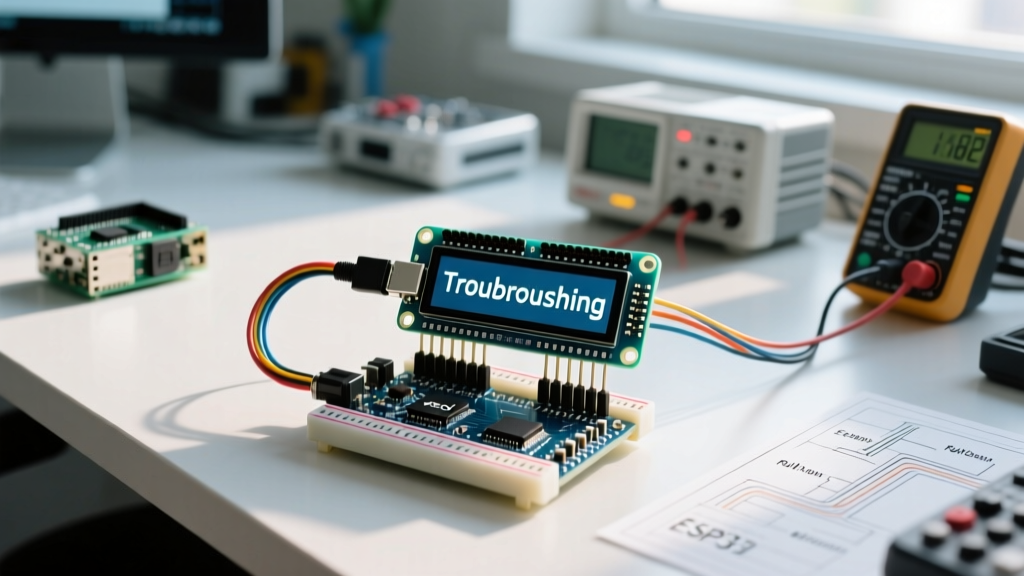

The Ultimate Diagnostic Guide for HD44780 and I2C LCD Modules
Despite the rise of OLED and TFT screens, the classic 16x2 and 20x4 character LCD display for Arduino remains an absolute staple in 2026 for DIY solar charge controllers, weather stations, and industrial control panels. They are highly legible in direct sunlight, consume minimal power, and cost between $3.50 (parallel) and $8.00 (I2C backpack variants). However, their ubiquitous Hitachi HD44780 controller architecture is notorious for frustrating beginners with blank screens, single rows of white boxes, or scrolling garbage text.
This troubleshooting guide bypasses generic advice and dives straight into the electrical realities, exact voltage thresholds, and silicon-level quirks of LCD modules. Whether you are wiring a standard 16-pin parallel interface or using a PCF8574 I2C backpack, follow this systematic diagnostic flow to isolate your failure point.
Symptom 1: Completely Blank Screen (No Backlight, No Text)
If your LCD display for Arduino is entirely dark, the issue is almost exclusively a power delivery or backlight circuit failure. Before questioning your code, grab a multimeter.
Step 1: Verify VSS and VDD Polarity
Pin 1 (VSS) is Ground, and Pin 2 (VDD) is +5V. Reversing these will not immediately destroy the HD44780 chip, but it will prevent the internal logic gate oscillator from starting. Measure across Pin 1 and Pin 2 directly at the LCD header. You must read 4.8V to 5.2V. If you read negative voltage, swap your wires.
Step 2: The Backlight Current Limiting Trap
Pins 15 (Anode) and 16 (Cathode) power the LED backlight. On premium 2026 modules, a 10Ω or 22Ω surface-mount current-limiting resistor is pre-soldered on the PCB. However, many ultra-cheap clone boards omit this resistor. If you apply 5V directly to Pin 15 on a board lacking this resistor, you will instantly blow the backlight LED or trip the Arduino Uno's 500mA USB polyfuse.
Expert Fix: If your multimeter shows 0V across the backlight pins but 5V at the source, test the LED with a 3.3V logic probe. If it remains dead, the internal trace fuse is blown. For future builds, always place a 22Ω resistor in series with Pin 15 when using unverified clone boards.
Symptom 2: Backlight is ON, but Screen Shows 'White Boxes' on Row 1
This is the most common hardware initialization failure. The white boxes indicate that the HD44780 controller has successfully powered up, cleared the Display Data RAM (DDRAM), and set the default memory cursor—but the Arduino has failed to push any character data to the bus.
The Contrast Voltage (V0) Misconception
Pin 3 (V0) controls the liquid crystal bias voltage. Most tutorials tell you to 'twist the blue potentiometer until text appears.' This is imprecise. The liquid crystals require a very specific delta-voltage relative to VDD to twist and block the backlight.
- Target Voltage: Measure Pin 3 relative to Pin 1 (GND). The optimal voltage is between 0.45V and 0.85V.
- Above 1.2V: The screen will appear completely blank (crystals are fully relaxed, passing all light).
- Below 0.2V: The entire screen will turn solid black/dark blue (crystals are fully twisted, blocking all light).
If turning the potentiometer does not yield a 0.5V reading, the wiper pin on the trimmer is likely floating or broken. Bypass the pot entirely by wiring a 1kΩ resistor from Pin 3 to GND to force a ~0.6V drop.
The Floating RW Pin (Parallel Mode Only)
If you are using a 16-pin parallel connection (not I2C), Pin 5 is the RW (Read/Write) select pin. The Arduino LiquidCrystal Reference assumes you are only writing to the display. If Pin 5 is left unconnected, it acts as an antenna, picking up electromagnetic noise from nearby PWM motor drivers or switching regulators. This noise randomly toggles the LCD into 'Read' mode, causing a bus collision with the Arduino's data pins.
The Fix: Hard-tie Pin 5 (RW) directly to GND. Never leave it floating.
Symptom 3: Garbage Text, Random Characters, or I2C Failures
When using an I2C backpack (which reduces wiring from 12 pins down to 4), garbage text or complete unresponsiveness is almost always an addressing or library mismatch. The I2C expander chip on the back of the LCD translates serial I2C data into parallel HD44780 signals.
Identifying the Expander Chip Address
According to the NXP PCF8574 Datasheet, the base I2C address is determined by the state of the A0, A1, and A2 pins on the silicon. Manufacturers use two primary variants for LCD backpacks:
| Expander Chip Model | Default Hex Address | Common Silkscreen Markings | LiquidCrystal_I2C Init Code |
|---|---|---|---|
| PCF8574 (NXP/TI) | 0x27 | PCF8574, SM, no 'A' suffix | LiquidCrystal_I2C lcd(0x27, 16, 2); |
| PCF8574A (NXP/TI) | 0x3F | PCF8574A, SM-A | LiquidCrystal_I2C lcd(0x3F, 16, 2); |
If your code specifies 0x27 but your board uses the 'A' variant chip, the Arduino will send data into the void, and the LCD will either remain blank or display the last initialized memory state (often garbage characters).
Running an I2C Bus Scanner
Do not guess the address. Use an I2C scanner sketch to poll the bus. As outlined in SparkFun's comprehensive I2C guide, the I2C protocol requires devices to acknowledge (ACK) their address. Upload the standard Wire.h scanner sketch to your Arduino. If the serial monitor returns 'No I2C devices found', your hardware is at fault:
- Missing Pull-up Resistors: While many Arduino boards have internal 10kΩ pull-ups on A4/A5, long cable runs to the LCD require external 4.7kΩ pull-up resistors on both SDA and SCL lines to prevent signal degradation.
- Voltage Mismatch: If you are using a 3.3V Arduino (like the Due or Zero) but powering the LCD backpack with 5V, the I2C logic high threshold will mismatch. Use a bidirectional logic level converter (e.g., BSS138 MOSFET module, ~$1.50) between the 3.3V SDA/SCL pins and the 5V LCD backpack.
Symptom 4: Text Fades, Flickers, or Resets During Motor Operations
If your LCD display for Arduino works perfectly on the bench but resets or flickers when installed in a chassis with relays, stepper motors, or solenoids, you are experiencing voltage sag and inductive kickback.
Power Starvation on the 5V Rail
A 20x4 LCD with a full white backlight can draw up to 180mA. If you are powering the Arduino via USB, a standard PC USB port limits current to 500mA. When a relay coil engages, it can pull an additional 150mA, causing the Arduino's onboard 5V linear regulator to drop to 4.2V. The HD44780 controller requires a minimum of 4.5V to maintain DDRAM state. When voltage dips below this, the LCD performs a hard hardware reset, resulting in a flicker or a return to the default white-box state.
Hardware Mitigation: Place a 470µF electrolytic capacitor directly across the VDD and VSS pins on the LCD header. This local energy reservoir will sustain the LCD controller through millisecond-scale voltage sags caused by inductive loads.
Quick-Reference Troubleshooting Matrix
| Visual Symptom | Primary Suspect | Diagnostic Action |
|---|---|---|
| Completely Dark | Power / Backlight LED | Check 5V at Pin 2. Test Pin 15 with 3.3V. |
| Row 1 White Boxes | Data Bus / RW Pin | Tie Pin 5 to GND. Verify D4-D7 continuity. |
| Solid Black Screen | Contrast Too High | Adjust V0 (Pin 3) to ~0.6V relative to GND. |
| Garbage / Random Text | I2C Address Mismatch | Run I2C Scanner. Check for 0x27 vs 0x3F. |
| Flickering / Resetting | Voltage Sag / Noise | Add 470µF cap across LCD VDD/VSS pins. |
Final Thoughts on LCD Longevity
When properly biased and powered, an HD44780-based LCD display for Arduino will easily outlast the microcontroller itself, often running for decades in embedded commercial products. By focusing on exact V0 voltage thresholds, hard-tying the RW pin, and verifying I2C expander silicon variants, you eliminate 99% of the 'broken screen' issues that plague DIY electronics projects. Always measure before you code.