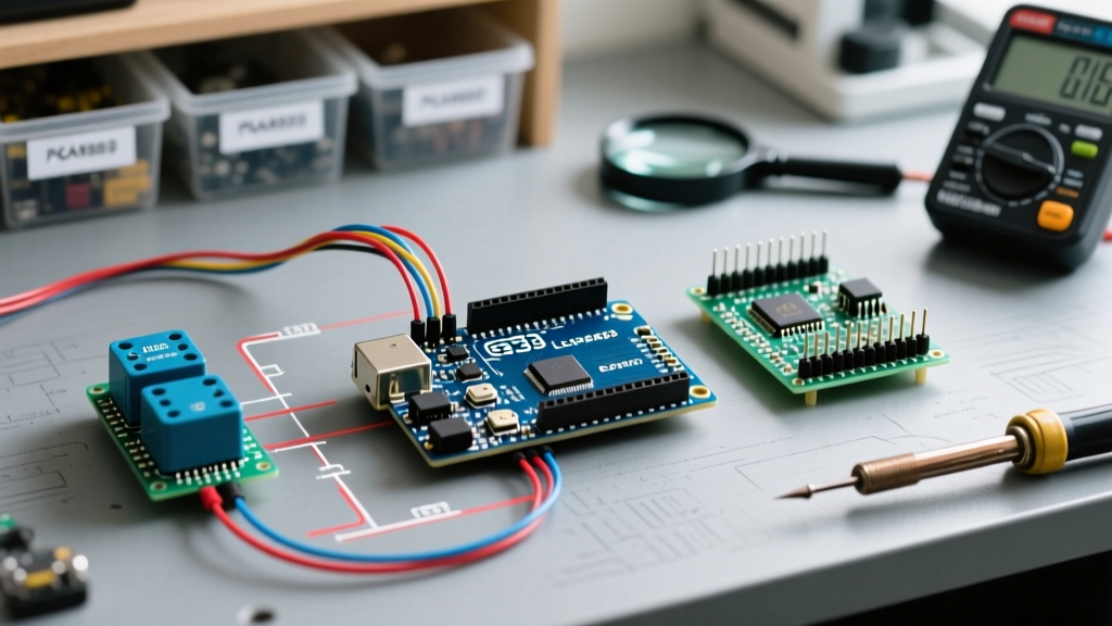

Most hobbyists treat a relay for Arduino as a simple digital toggle: send a HIGH signal, and the circuit closes. However, in precision automation, scientific data logging, or phase-sensitive motor control, treating an electromechanical or solid-state switch as an 'instant' digital component leads to catastrophic timing errors, missed interrupts, and hardware degradation. Calibrating a relay module is not about analog scaling; it is about characterizing temporal latency, contact bounce envelopes, coil voltage thresholds, and isolation integrity.
As of 2026, the market is flooded with ultra-cheap clone relay modules that exhibit wild variances in switching times and coil tolerances. This guide provides a deep-dive calibration framework to ensure your microcontroller's peripheral switching is accurate, repeatable, and safe.
The Myth of the Instant Switch: Temporal Calibration
When an electromechanical relay (EMR) coil is energized, the armature physically travels across an air gap to strike the contacts. This mechanical collision causes the contacts to bounce, rapidly making and breaking the circuit before settling. If your Arduino is reading a sensor triggered by a relay, or if you are switching a sensitive digital bus, this bounce can register as dozens of false triggers.
Conversely, Solid State Relays (SSRs) eliminate physical bounce but introduce their own timing inaccuracies, particularly regarding zero-crossing detection latency. Below is a calibration baseline for the most common relay modules used in Arduino ecosystems.
| Relay Model | Type | Nominal Coil Voltage | Typical Bounce / Latency | Must-Operate Voltage (MOV) |
|---|---|---|---|---|
| Songle SRD-05VDC-SL-C (Standard Blue Module) | EMR | 5V DC | 8ms - 15ms | 3.75V (75% of Nominal) |
| Omron G5V-2-DC5 (High-Reliability) | EMR | 5V DC | 3ms - 5ms | 3.75V (75% of Nominal) |
| Fotek SSR-25DA (Zero-Crossing) | SSR | 3-32V DC | 0ms bounce / up to 8.3ms latency | 2.5V DC (Input Threshold) |
| Omron G3MB-202P (Random Fire SSR) | SSR | 5V DC | < 100µs | 3.5V DC |
Measuring Your Specific Batch
Do not rely on datasheet averages for cheap EMR modules. To calibrate your specific batch, wire the relay's common (COM) and normally open (NO) pins to an Arduino digital input with an internal pull-up resistor. Use the micros() function inside a hardware interrupt to log the time delta between the first falling edge and the final stable state. For a comprehensive software approach to this, refer to the Arduino Official Debounce Tutorial, which outlines state-machine logic for filtering these mechanical anomalies.
Voltage Threshold Calibration: Pull-In and Dropout
A frequent point of failure in Arduino projects is powering a 5V relay module directly from the microcontroller's 5V pin. Under load, USB voltage sag can drop the supply to 4.6V or lower. While this is above the typical 75% Must-Operate Voltage (MOV) threshold of 3.75V, it severely impacts the optocoupler's Current Transfer Ratio (CTR) on the module's input side.
Expert Insight: A degraded optocoupler CTR increases the turn-on latency of the relay coil. If your timing-critical application relies on a precise 10ms pulse, a sagging input voltage combined with an aging optocoupler can stretch that pulse to 14ms, causing downstream synchronization failures.
Bench Calibration Procedure
- Isolate the Coil: Disconnect the relay module from the Arduino. Connect it to a variable benchtop power supply.
- Sweep for Pull-In: Slowly increase the voltage from 0V. Use a multimeter in continuity mode on the COM and NO pins. Record the exact voltage where the contacts close (Pull-In).
- Sweep for Dropout: Slowly decrease the voltage from 5V. Record the exact voltage where the contacts open (Must-Release Voltage, typically 10% of nominal, or 0.5V).
- Calculate the Hysteresis Gap: The difference between Pull-In and Dropout is your safe operating hysteresis. If your Arduino's logic HIGH output is close to the Pull-In threshold, you must use a dedicated external 5V power supply for the relay module's VCC, sharing only the GND and signal pins with the Arduino.
Solid State Relays (SSR) and Zero-Crossing Accuracy
When switching AC loads, zero-crossing SSRs like the Fotek SSR-25DA are standard because they minimize inrush current and electromagnetic interference (EMI). However, they introduce a unique timing inaccuracy. A zero-crossing SSR will not turn on until the AC sine wave crosses 0V.
If your Arduino sends a trigger signal at a random point in the 60Hz AC cycle, the SSR will wait up to 8.33 milliseconds (half a cycle) to actually close the circuit. For applications like precision phase-angle control of heating elements or dimming, this latency is unacceptable. As detailed in DigiKey's TechZone guide on Solid-State Relays, you must select a 'random-fire' SSR for phase-control applications and synchronize your Arduino's trigger pulses using a hardware zero-crossing detection interrupt circuit.
Software Calibration: Dynamic Debounce Measurement
Hardcoding a delay(50) to handle relay bounce is inefficient and blocks the microcontroller. Instead, calibrate your software using a non-blocking timestamp comparison. Below is a structural logic flow for a dynamic debounce calibration routine:
// Non-blocking dynamic debounce calibration logic
unsigned long lastDebounceTime = 0;
unsigned long debounceDelay = 5; // Start with 5ms, calibrate via serial monitor
int reading;
int previousReading = HIGH;

void loop() {
  reading = digitalInterruptRead(RELAY_SENSE_PIN);

  if (reading != previousReading) {
    lastDebounceTime = millis();
  }

  if ((millis() - lastDebounceTime) > debounceDelay) {
    // State is stable, execute precision logic here
    if (reading != relayState) {
      relayState = reading;
      logSwitchingEvent(micros());
    }
  }
  previousReading = reading;
}
By logging the micros() timestamp of every state change to an SD card or serial buffer, you can graph the bounce envelope of your specific relay for Arduino setup and dynamically adjust the debounceDelay variable to the exact millisecond required, optimizing CPU cycle usage.
Failure Modes and Accuracy Degradation Matrix
Relay accuracy is not static; it degrades over time due to environmental and electrical stress. Use the following troubleshooting matrix to diagnose calibration drift in your peripheral circuits.
| Symptom | Root Cause | Calibration / Hardware Fix |
|---|---|---|
| Increasing turn-on latency over months of use | Optocoupler CTR degradation due to continuous forward current stress. | Reduce input LED current via a larger current-limiting resistor; replace optocoupler with a high-CTR variant (e.g., PC817X). |
| Erratic bounce times exceeding 20ms | Contact oxidation or carbon buildup from arcing inductive loads. | Implement an RC snubber network across the load; calibrate software debounce to 30ms or replace EMR with an SSR. |
| Relay fails to release (contacts welded) | Inrush current exceeded the relay's maximum switching capacity. | Derate relay capacity by 50% for inductive loads; add a negative temperature coefficient (NTC) thermistor to limit inrush. |
| SSR output leaks current when 'OFF' | Inherent leakage current of the TRIAC/MOSFET output stage. | Add a bleeder resistor across the load; consult the Omron Relay Technical Guide for specific leakage specs. |
Final Calibration Best Practices
Achieving true accuracy with a relay for Arduino requires moving beyond the 'plug-and-play' mentality. Always power relay coils from a dedicated, decoupled voltage rail to prevent back-EMF from resetting your microcontroller. Measure your specific module's bounce time rather than trusting forum averages, and always match the relay's physical switching characteristics (EMR vs. Zero-Cross SSR vs. Random-Fire SSR) to the exact temporal requirements of your load. By treating your relay module as a precision electromechanical instrument rather than a simple digital switch, you ensure long-term reliability and data integrity in your embedded systems.