
The Reality of Mains Voltage Switching
Integrating a relay Arduino module into a home automation or industrial monitoring project is a rite of passage for electronics enthusiasts. However, moving from toggling a 5V LED to switching a 120V AC sump pump or window air conditioner introduces severe safety and engineering challenges. In 2026, while microcontroller logic has become more robust, the physics of electromechanical contacts and inductive kickback remain unchanged. This guide bypasses basic tutorials to focus on real-world, high-load relay integration, emphasizing galvanic isolation, contact protection, and failure mitigation.
Safety Warning: According to the U.S. Consumer Product Safety Commission, improper mains wiring and overloaded switching components are leading causes of residential electrical fires. Always treat 120V/240V AC with extreme caution, use properly rated enclosures, and ensure your low-voltage DC logic is physically isolated from high-voltage AC lines.
Anatomy of the Standard 5V Relay Module
The ubiquitous blue 5V relay module found in most starter kits typically houses a Songle SRD-05VDC-SL-C electromechanical relay (EMR). While adequate for resistive loads like incandescent bulbs or heating elements up to 10A, its 10A rating degrades significantly when switching inductive or capacitive loads.
The JD-VCC Jumper: A Critical Isolation Detail
Most standard modules feature a three-pin header with a jumper labeled JD-VCC, VCC, and GND. Many makers leave this jumper in place, powering the relay coil directly from the Arduino's 5V rail. This is a critical mistake for high-reliability applications.
- Jumper Installed: The relay coil shares a ground and power rail with your microcontroller. Switching transients and coil collapse can inject noise directly into the Arduino's voltage regulator, causing brownouts or random resets.
- Jumper Removed (True Isolation): By removing the jumper, you can power the
JD-VCCandGNDpins from an independent 5V power supply. The Arduino only connects to theINpin. The onboard PC817 optocoupler then bridges the two domains using light, providing true galvanic isolation. For a deeper dive into electromechanical switching physics and optocoupler schematics, the SparkFun Relay Tutorial provides excellent foundational diagrams.
Real-World Scenario: Switching a 120V AC Sump Pump
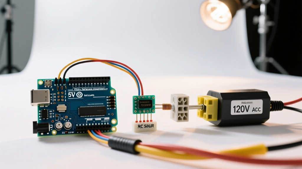
A sump pump is a notoriously difficult load. It features a high inrush current (often 4x to 6x the running current) and generates massive back-EMF when the motor stops. Here is how to engineer a reliable relay Arduino interface for this specific application.
Component Bill of Materials (2026 Pricing)
| Component | Specification | Est. Cost (2026) | Purpose |
|---|---|---|---|
| Omron G5LE-14-DC5 | 10A 250VAC, 5V Coil, Sealed | $3.85 | High-reliability EMR (Superior to Songle) |
| Fotek SSR-25DA | 25A, 3-32V DC to 24-380V AC | $11.50 | Solid State Alternative for high inrush |
| RC Snubber Network | 0.1µF X2 Cap + 100Ω 1/2W Resistor | $1.20 | Suppresses AC inductive voltage spikes |
| 14 AWG Stranded Wire | THHN or Silicone, 600V rated | $0.45/ft | Safe mains routing for 15A circuits |
Wiring the Mains Side
When wiring the 120V AC side, you must only switch the HOT (Line) wire. The Neutral wire should be spliced directly to the load. Switching the Neutral leaves the load energized at 120V even when the relay is open, creating a severe shock hazard during maintenance.
- Route the 14 AWG HOT wire from your mains breaker into the relay's
COM(Common) terminal. - Connect a 14 AWG wire from the
NO(Normally Open) terminal to the HOT input of the sump pump. - Install the RC snubber network directly across the
COMandNOterminals. The 0.1µF capacitor must be an X2-rated safety capacitor designed for continuous across-the-line AC use; standard ceramic or electrolytic capacitors will short and catch fire.
Failure Modes: Why Relays Weld and Fry
Understanding why relays fail is the hallmark of an experienced embedded systems engineer. When a relay Arduino setup fails in the field, it is rarely the microcontroller's fault.
Contact Welding and Pitting
When opening a circuit with an inductive load like a motor, the collapsing magnetic field attempts to keep current flowing. This results in an electrical arc across the separating relay contacts. Over time, this arc vaporizes the contact material (pitting) or melts them together (welding). If your sump pump relay welds shut, the pump will run continuously until it burns out or floods your basement.
The Fix: The aforementioned RC snubber absorbs the inductive spike. For extremely high inrush loads, bypass the EMR entirely and use a Zero-Crossing Solid State Relay (SSR) like the Fotek SSR-25DA, which switches the AC load only when the sine wave crosses 0V, eliminating arcing entirely.
Flyback Diode Failure on the DC Side
On the low-voltage DC side, the relay coil is an inductor. When the Arduino GPIO pin pulls the optocoupler transistor low, cutting power to the coil, the collapsing magnetic field generates a reverse voltage spike that can exceed 100V. If the module's flyback diode (usually a 1N4007) is missing or fails open, this spike will destroy the optocoupler and potentially back-feed into the Arduino's GPIO pin.
When configuring your microcontroller pins to drive these optocouplers, refer to the official Arduino Digital Pins documentation to ensure your specific board's GPIO can safely sink the required LED current (typically 5mA to 20mA) without exceeding maximum per-pin limits.
Troubleshooting Matrix
| Symptom | Probable Cause | Engineering Solution |
|---|---|---|
| Arduino resets when relay clicks | Voltage sag from coil inrush / Shared ground noise | Remove JD-VCC jumper; use isolated 5V supply for relay module. |
| Relay hums or chatters loudly | Insufficient coil drive voltage or failing diode | Verify 4.8V-5.2V at module VCC under load; replace flyback diode. |
| Load stays ON after GPIO goes LOW | Contacts welded due to AC inductive arcing | Install X2 RC snubber; upgrade to higher ampacity relay or SSR. |
| Optocoupler LED burns out | Missing current-limiting resistor on IN pin | Some cheap modules omit the base resistor; add 1kΩ in series. |
Software Implementation: Non-Blocking State Management
In real-world applications, using the delay() function to time relay states is unacceptable, as it halts sensor polling and network communication. Instead, implement a state machine using millis().
Furthermore, mechanical relays suffer from 'contact bounce'—though less critical when switching heavy AC loads compared to reading pushbuttons, rapid toggling in your code can cause the relay to chatter. Implement a software debounce or a minimum state-lockout time (e.g., 500ms) in your firmware to prevent the Arduino from rapidly cycling the relay coil, which drastically reduces the mechanical lifespan of the spring and armature.
Summary
A successful relay Arduino project requires looking beyond the basic digitalWrite(HIGH) command. By implementing true optical isolation via the JD-VCC jumper, utilizing X2-rated RC snubbers for inductive AC loads, and selecting the appropriate contact material or SSR for your specific amperage, you transition from a fragile prototype to a robust, deployment-ready system.