
The Anatomy of a PIR Module: Beyond the Dome
Integrating a PIR sensor with an Arduino is a foundational skill for motion-activated lighting, security systems, and automated wildlife cameras. However, most tutorials treat the sensor as a simple digital switch, leading to erratic behavior in real-world deployments. To build reliable systems, you must understand the underlying hardware.
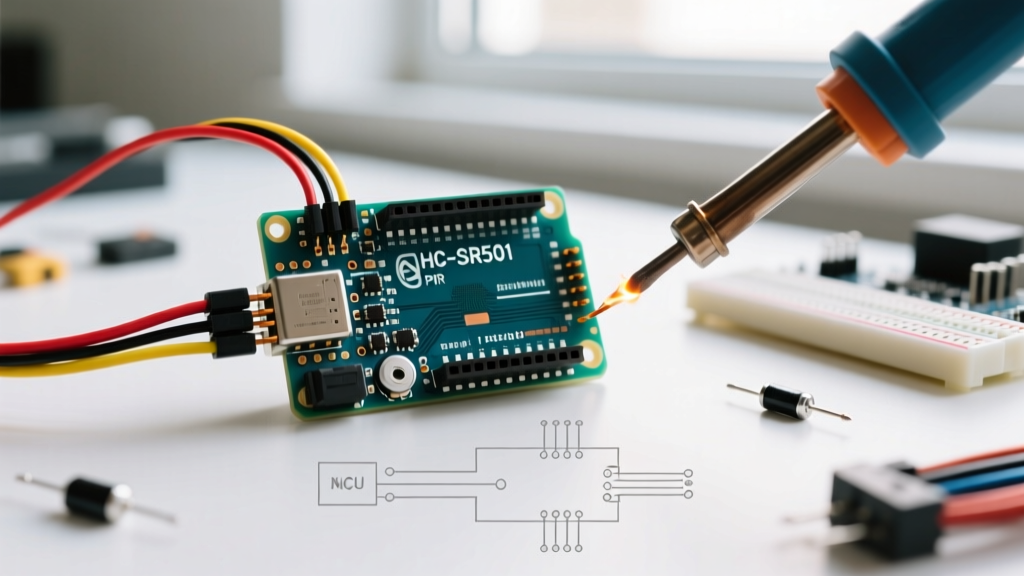
The standard HC-SR501 module relies on a pyroelectric sensor (usually the RE200B) paired with a BISS0001 micro-power PIR motion detector IC. The pyroelectric element detects changes in infrared radiation (heat) across its dual sensing elements. The BISS0001 processes these minute analog voltage fluctuations, applies bandpass filtering (typically 0.3Hz to 7Hz to isolate human walking speeds), and outputs a clean 3.3V digital HIGH signal when a threshold is crossed.
Critical Insight: The BISS0001 operates strictly at 3.3V. The HC-SR501 module includes an onboard LDO voltage regulator (often a 7133 or similar) to drop the 5V input down to 3.3V. Understanding this architecture is the key to solving the most common power-related false triggers.
Module Comparison Matrix (2026 Market)
While the HC-SR501 remains the default choice for breadboarding, modern 2026 supply chains have made compact alternatives highly accessible. Choose your module based on your project's spatial and power constraints.
| Module | IC / Sensor | Price Range (2026) | Detection Range | Adjustability | Best Use Case |
|---|---|---|---|---|---|
| HC-SR501 | BISS0001 + RE200B | $1.50 - $3.00 | Up to 7m (120°) | Pots for Time/Sens, Jumper | Prototyping, Room-scale security |
| HC-SR505 | BISS0001 + RE200B | $2.00 - $3.50 | Up to 3m (100°) | Fixed (8s delay) | Compact wearables, hidden nodes |
| AM312 | Integrated SoC | $1.80 - $2.50 | Up to 3m (120°) | Fixed (2s delay) | Ultra-low power battery IoT |
Hardware Wiring & The 3.3V Trap
Wiring the HC-SR501 to an Arduino Uno or Nano is straightforward, but power delivery requires strict attention.
- VCC: Connect to the Arduino's 5V pin. Do not connect this to the 3.3V pin. The onboard LDO requires a minimum dropout voltage (usually ~1.2V) to regulate down to 3.3V. Feeding it 3.3V directly will cause the BISS0001 to brownout, resulting in a permanently HIGH or erratically flickering output pin.
- GND: Connect to Arduino GND. Ensure this shares a common ground plane with your microcontroller to prevent ground loops.
- OUT: Connect to Arduino Digital Pin 2. This pin outputs 3.3V when motion is detected, which is safely above the 2.0V logic HIGH threshold for 5V AVR microcontrollers (like the ATmega328P) and perfectly native for 3.3V boards (like the ESP32).
Calibrating the Potentiometers & Jumper
The HC-SR501 features two orange trimpots and a three-pin jumper block. Factory settings are rarely optimal for specific environments.
- Sensitivity (Sx) Potentiometer: Adjusts the detection distance and angular width. Turning it fully clockwise maximizes range (~7 meters) and widens the detection cone. Turn it counter-clockwise to restrict the zone to ~3 meters, which is vital for preventing triggers from adjacent hallways.
- Time Delay (Tx) Potentiometer: Dictates how long the OUT pin stays HIGH after motion ceases. The range is logarithmic, spanning from roughly 0.3 seconds (fully counter-clockwise) to over 200 seconds (fully clockwise). For Arduino integration, set this to the minimum (0.3s) and handle timing logic in your code for precise control.
- Trigger Mode Jumper:
- H (High/Retrigger): The output stays HIGH as long as continuous motion is detected. The timer resets with every new movement. Use this for 95% of Arduino projects.
- L (Low/Non-Retrigger): The output goes HIGH for the Tx duration, then forcibly goes LOW for a ~2.5 second blocking period, ignoring all motion. Useful for strict duty-cycle lighting.
Non-Blocking Arduino Code with Software Debounce
Beginners often use delay() to wait out the sensor's timing, which halts the microcontroller. Furthermore, PIR sensors occasionally output microsecond-level LOW dips during a continuous HIGH state due to signal noise at the edges of the Fresnel lens. The code below implements a non-blocking state machine with a 50ms software debounce filter to ensure rock-solid state changes.
const int PIR_PIN = 2;
const unsigned long DEBOUNCE_TIME = 50; // 50ms debounce filter

bool currentMotionState = false;
bool lastMotionState = false;
unsigned long lastDebounceTime = 0;

void setup() {
  Serial.begin(115200);
  pinMode(PIR_PIN, INPUT);
  Serial.println("PIR Sensor Initializing...");
}

void loop() {
  // Read the raw sensor state
  bool reading = digitalRead(PIR_PIN);

  // Software debounce logic
  if (reading != lastMotionState) {
    lastDebounceTime = millis();
  }

  if ((millis() - lastDebounceTime) > DEBOUNCE_TIME) {
    if (reading != currentMotionState) {
      currentMotionState = reading;

      if (currentMotionState == HIGH) {
        Serial.println("[EVENT] Motion Detected - Zone Active");
        // Trigger your relay, LED, or MQTT payload here
      } else {
        Serial.println("[EVENT] Motion Ceased - Zone Clear");
        // Trigger timeout logic here
      }
    }
  }
  lastMotionState = reading;
}
Advanced Troubleshooting: Eliminating False Triggers
If your PIR sensor is firing randomly without human presence, you are likely encountering one of three specific failure modes.
1. The Initialization Lockout (The 30-Second Rule)
Upon receiving power, the BISS0001 chip requires 30 to 60 seconds to sample the ambient infrared environment and establish a baseline. If motion occurs, or if the voltage fluctuates during this window, the sensor will latch HIGH or trigger falsely. Fix: Implement a 60-second software lockout in your setup() routine before enabling motion interrupts.
2. RF Interference from Wi-Fi/Bluetooth Radios
When pairing a PIR sensor with an ESP32 or ESP8266, the sudden current spike during Wi-Fi transmission (up to 300mA) causes micro-sags on the 5V rail. The PIR's LDO struggles to compensate, causing the BISS0001 to reset and output a false HIGH. Fix: Solder a 100µF electrolytic capacitor and a 0.1µF ceramic capacitor directly across the VCC and GND pins on the PIR module itself to provide local transient current buffering.
3. Thermal Drafts and the Fresnel Lens
PIR sensors do not detect humans; they detect changes in thermal radiation. An HVAC vent blowing hot air across a cold wall, or direct sunlight shifting through a window, will trigger the sensor. Furthermore, if the white HDPE Fresnel dome is scratched, dirty, or seated too far from the pyroelectric element, the focal geometry is destroyed, reducing range by up to 80%. Keep the dome pristine and avoid aiming the sensor at heat sources.
Low-Power Integration Using Hardware Interrupts
For battery-powered Arduino nodes (e.g., ATmega328P running on a LiPo), polling the PIR pin wastes milliamps of current. Instead, utilize hardware interrupts and AVR sleep modes. Because the HC-SR501 outputs a clean, sustained HIGH signal, we can wake the microcontroller on a RISING edge.
According to the official Arduino attachInterrupt() reference, you must map the physical pin to the correct interrupt vector. On an Uno, Digital Pin 2 is INT0.
#include <avr/sleep.h>

void wakeUp() {
  // ISR (Interrupt Service Routine) - keep it empty and fast
}

void setup() {
  pinMode(2, INPUT);
  // Attach interrupt to wake from sleep
  attachInterrupt(digitalPinToInterrupt(2), wakeUp, RISING);
}

void loop() {
  // Go to deep sleep
  set_sleep_mode(SLEEP_MODE_PWR_DOWN);
  sleep_enable();
  sleep_mode(); // CPU halts here, drawing ~1.5mA total system current

  // Execution resumes here when PIR goes HIGH
  sleep_disable();

  // Execute motion logging, transmit via LoRa, then return to sleep
  transmitMotionEvent();
}
By combining the HC-SR501's inherent low quiescent current (~50µA) with the ATmega328P's power-down sleep mode, a motion-activated node can run for over a year on a standard 2000mAh 18650 lithium cell, making it a highly efficient solution for remote environmental monitoring.