
The Core Dilemma: Choosing the Right Switching Peripheral
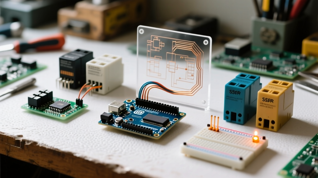
When building home automation systems, industrial controllers, or high-power switching rigs, the combination of an arduino and relay board remains the most ubiquitous prototyping standard in 2026. However, not all relay modules are created equal. Makers and engineers frequently default to the cheapest blue-cube electromechanical boards without considering the electrical realities of their specific loads. Switching a 12V DC LED strip requires a fundamentally different approach than toggling a 240V AC inductive motor.
This comprehensive component comparison dissects the two dominant architectures: Electromechanical Relay (EMR) modules and Solid State Relay (SSR) modules. We will bypass generic marketing specs and dive into the silicon, the optocoupler isolation circuits, and the real-world failure modes that destroy microcontrollers.
Electromechanical Relay (EMR) Boards: The Songle Standard
The vast majority of 1-channel, 4-channel, and 8-channel relay boards on the market utilize the Songle SRD-05VDC-SL-C electromechanical relay. Recognizable by its blue plastic casing, this component is a workhorse for general-purpose AC/DC switching.
Internal Circuitry and GPIO Limits
An ATmega328P (the brain of the Arduino Uno) GPIO pin can safely source or sink a maximum of 20mA. The Songle 5V relay coil has a resistance of approximately 70 ohms, demanding roughly 71mA to energize the electromagnetic field and pull the mechanical contact. Direct connection will instantly brownout the microcontroller or fry the GPIO trace.
To solve this, standard EMR boards include a driver circuit consisting of:
- PC817 Optocoupler: Provides galvanic isolation between the low-voltage logic and the high-voltage coil.
- S8050 NPN Transistor: Acts as a switch to handle the 71mA coil current.
- 1N4148 Flyback Diode: Clamps the reverse voltage spike (back-EMF) generated when the magnetic field collapses.
According to the Arduino Official Relay Guide, utilizing this onboard driver circuit is mandatory for safe operation. A typical 4-channel EMR board costs between $2.50 and $4.00 in 2026, making it highly accessible.
Solid State Relay (SSR) Boards: The Silicon Route
For applications demanding high switching frequencies, silent operation, or immunity to contact arcing, Solid State Relay modules are the superior choice. The most common Arduino-compatible SSR boards utilize the Omron G3MB-202P or similar Fotek TRIAC-based chips.
Zero-Cross Switching and Thermal Realities
Unlike mechanical contacts that physically slam together, SSRs use light-activated TRIACs to switch AC loads. The G3MB-202P features built-in zero-cross detection, meaning it only triggers the load when the AC sine wave passes through 0V. This drastically reduces Electromagnetic Interference (EMI) and inrush current spikes.
However, SSRs introduce a new physical constraint: heat. A mechanical relay has near-zero resistance when closed. An SSR exhibits a forward voltage drop of roughly 1.2V to 1.6V. If you switch a 2A AC load, the SSR dissipates approximately 3.2 Watts of heat (1.6V × 2A). As noted in the Omron Solid State Relay Technical Portal, operating an SSR without an adequate heatsink at this wattage will trigger the chip's internal thermal shutdown or cause catastrophic silicon failure within minutes. Cheap 4-channel Arduino SSR boards rarely include heatsinks, artificially limiting their practical continuous load to about 0.5A per channel unless you modify the hardware.
The JD-VCC Jumper: A Masterclass in Opto-Isolation
One of the most critical, yet widely misunderstood, features on standard 4-channel and 8-channel EMR boards is the JD-VCC jumper. This small plastic shunt dictates how the board handles power and isolation.
Expert Warning: Leaving the JD-VCC jumper in place defeats the purpose of the optocouplers, tying your sensitive Arduino logic directly to the noisy relay coil power rail.
How to Wire for True Isolation
- Remove the JD-VCC jumper from the VCC and JD-VCC pins on the relay board.
- Connect the Arduino's 5V pin to the board's VCC pin (this powers the optocoupler LEDs).
- Connect the Arduino's GND to the board's GND pin.
- Provide a separate 5V power supply to the JD-VCC pin and the board's secondary GND pin. This separate supply powers the actual relay coils.
By doing this, if a massive back-EMF spike breaches the flyback diode, it only destroys the secondary power supply, not your Arduino's voltage regulator or microcontroller.
Component Comparison Matrix
To help you select the right module for your 2026 project architecture, review the empirical data below comparing standard market modules.
| Feature | EMR Board (Songle 5V) | SSR Board (G3MB-202P) | MOSFET Module (IRF520) |
|---|---|---|---|
| Switching Speed | ~10ms (Slow) | <1ms (Fast) | <1µs (Very Fast / PWM) |
| Max AC Voltage | 250VAC @ 10A | 240VAC @ 2A | N/A (DC Only) |
| Max DC Current | 30VDC @ 10A | N/A (AC Only) | 24VDC @ 5A |
| Contact Bounce | Yes (Mechanical) | No | No |
| Heat Generation | Negligible (at load) | High (Requires Heatsink) | Moderate (Linear Region) |
| Audible Noise | Loud Click | Silent | Silent |
| Typical Price (4-Ch) | $3.50 | $7.00 | $4.50 |
Real-World Failure Modes and Edge Cases
Theoretical datasheets rarely prepare you for the chaotic reality of inductive loads and counterfeit components. Here are the most common failure modes encountered in the field.
1. Contact Welding in EMRs
When switching highly inductive loads like AC motors, compressors, or large transformers, the initial inrush current can be 10x the nominal running current. When the EMR attempts to open the circuit, the collapsing magnetic field of the load sustains an electrical arc across the physical contacts. Over time, this arc melts the contact alloy, welding the relay permanently in the 'ON' position. For high-inductance loads, always consult Littelfuse Relay Application Guidelines and implement an external RC snubber network across the load.
2. SSR Leakage Current
Solid State Relays do not provide infinite resistance when turned off. The TRIAC inside the G3MB-202P leaks a small current, typically 1mA to 3mA. If you are switching a highly sensitive low-power LED bulb or a logic-level gate, this leakage can cause the load to ghost, flicker, or fail to power down completely.
3. Counterfeit Flyback Diodes
In the rush to manufacture sub-$2 relay boards, some overseas fabrication houses have been caught placing the 1N4148 flyback diode in reverse polarity. Instead of clamping the back-EMF spike, the reversed diode creates a dead short across the coil when energized, instantly vaporizing the S8050 transistor and sending 5V straight into the Arduino's logic pins. Always verify diode orientation with a multimeter on a new batch of cheap relay boards before wiring them to production hardware.
Decision Framework: Which Board for Your Project?
Use this actionable framework to finalize your peripheral selection:
- Choose EMR Boards if: You need to switch mixed AC/DC loads, require absolute zero leakage current when off, and are switching loads under 5A with low switching frequencies (e.g., turning a slow cooker or water pump on/off a few times a day).
- Choose SSR Boards if: You are switching purely resistive AC loads (like heating elements or incandescent bulbs), require silent operation for a consumer-facing device, or need to switch the load hundreds of times per minute where mechanical contacts would rapidly degrade.
- Choose MOSFET Modules if: Your project is strictly DC (e.g., 12V LED strips, PC fans, solenoids) and you require Pulse Width Modulation (PWM) for dimming or speed control. Neither EMRs nor SSRs can handle high-frequency PWM.
Understanding the precise electrical characteristics of your arduino and relay board pairing elevates your project from a fragile prototype to a robust, deployment-ready system. Always respect the isolation boundaries, calculate your thermal loads, and verify your flyback protection.