
The Multi-Peripheral Bottleneck in Robotics
When designing complex electromechanical projects—such as 6-DOF robotic arms, multi-axis camera gimbals, or automated greenhouse louvers—you quickly hit a hardware wall. Attempting to use an Arduino to control servo motor arrays directly via the microcontroller's native digital pins is a recipe for system instability. Native PWM pins are limited in number, and relying on the Arduino's hardware timers for multiple servos often causes conflicts with other critical peripherals like ultrasonic distance sensors (which require precise microsecond timing) or hardware serial communication.
Furthermore, in a multi-peripheral setup where your I2C bus is already populated with an SSD1306 OLED display and a BME280 environmental sensor, adding the electrical noise and current spikes of multiple servos directly to the MCU power rails will trigger brownouts, random I2C bus lockups, and erratic sensor readings. To build a robust, production-grade multi-peripheral rig in 2026, you must offload PWM generation and isolate your power domains.
The Solution: PCA9685 I2C PWM Driver
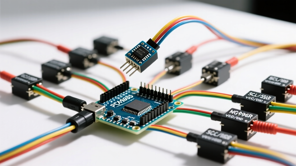
The industry-standard solution for driving up to 16 servos from a single I2C connection is the NXP PCA9685 chip, commonly available on breakout boards for $4.50 to $8.00. By utilizing an NXP PCA9685 dedicated PWM controller, you free up the Arduino's hardware timers and digital pins. The PCA9685 handles the 50Hz PWM signal generation internally via a 12-bit resolution register, communicating with the Arduino strictly over the I2C bus.
I2C Address Chaining for Massive Arrays
For larger multi-peripheral setups requiring more than 16 servos, the PCA9685 features six address-selection jumper pads (A0 through A5). This allows you to chain up to 62 modules on a single I2C bus, theoretically controlling 992 servos. However, be mindful of the I2C bus capacitance limit of 400pF. If you exceed this by daisy-chaining too many modules or using excessively long, unshielded wires alongside your OLED display, the bus will fail. Keep I2C traces under 30cm, or implement a PCA9615 I2C bus extender for long-distance runs.
Power Budgeting: The Most Common Point of Failure
The most catastrophic mistake beginners make when configuring an Arduino to control servo motor arrays is attempting to power the servos through the Arduino's 5V pin or the host PC's USB port. Servos draw massive transient currents when starting, stopping, or stalling under load. If you are integrating high-torque metal-gear servos alongside sensitive logic peripherals, a shared power rail will instantly drag the voltage below 4.5V, causing the Arduino's ATmega328P or ESP32 to reset continuously.
Servo Stall Current & Power Matrix (2026 Market Data)
| Servo Model | Type & Gear | Stall Current (5V-6V) | Holding Torque | 2026 Avg Price |
|---|---|---|---|---|
| TowerPro SG90 | Analog / Nylon | 700 mA | 1.8 kg-cm | $1.50 - $2.50 |
| TowerPro MG996R | Analog / Metal | 2,500 mA | 13.0 kg-cm | $6.00 - $9.00 |
| DS3218 | Digital / Metal | 3,200 mA | 20.0 kg-cm | $12.00 - $16.00 |
Expert Rule of Thumb: If you are driving four MG996R servos, your power supply must be capable of delivering at least 10 Amps continuous (4 x 2.5A) to handle simultaneous stall events without voltage sag. Use a dedicated 5V 10A (or higher) switching power supply, wiring the V+ and GND directly to the PCA9685's terminal block, completely bypassing the Arduino's voltage regulator.
Step-by-Step Wiring for Multi-Sensor Rigs
When integrating servos with other I2C peripherals like an OLED screen, proper wiring topology is essential to prevent signal degradation.
- Common Ground: Connect the GND of your dedicated servo power supply, the GND of the PCA9685 module, and the GND of the Arduino together. Without a common ground reference, the PWM signals will float, resulting in violent servo twitching.
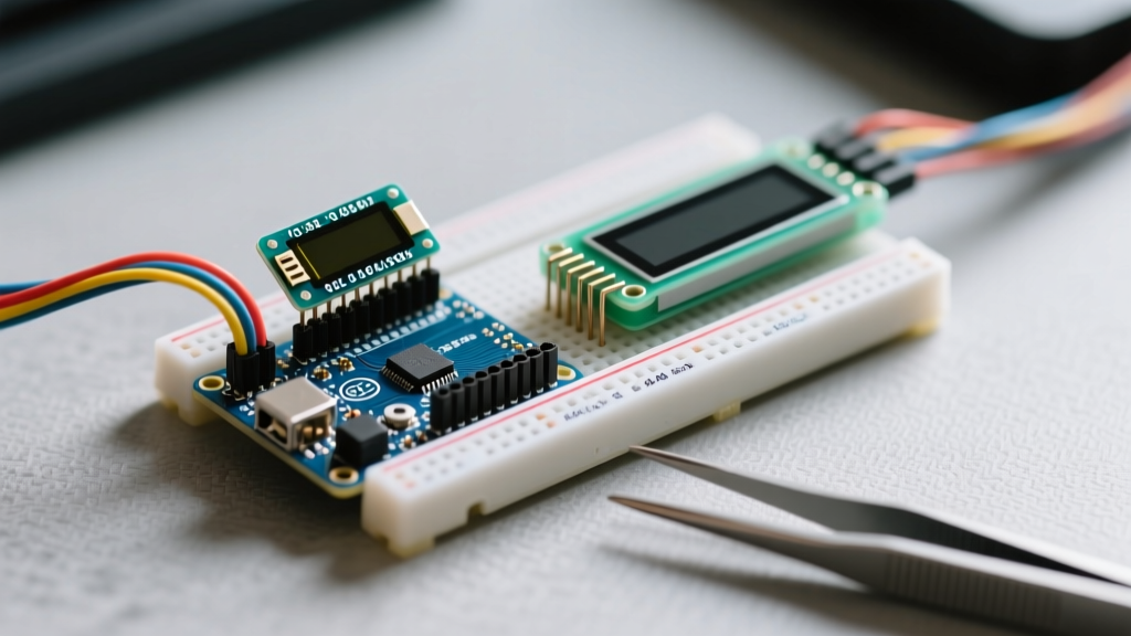
- I2C Bus Routing: Connect the Arduino SDA/SCL pins to the PCA9685 SDA/SCL pins. If using an SSD1306 OLED, wire it to the exact same SDA/SCL rails. Use 28 AWG twisted-pair wire for the I2C lines to reject electromagnetic interference (EMI) generated by the servo motors.
- Logic Level Shifting: If you are using a 3.3V microcontroller (like the ESP32 or Arduino Due) alongside 5V servos, the PCA9685 VCC pin (logic power) must be tied to 3.3V, while the V+ terminal block (servo power) receives 5V-6V. The PCA9685 is 5V tolerant on its I2C lines, making this level-shifting seamless.
- Decoupling Capacitors: Solder a 1000µF electrolytic capacitor directly across the V+ and GND screw terminals on the PCA9685 board. This acts as a local energy reservoir to absorb the microsecond current spikes when digital servos like the DS3218 switch states.
Eliminating Servo Jitter in Complex Networks
Troubleshooting Insight: If your servos exhibit a subtle, high-frequency jitter only when your OLED display is updating or an ultrasonic sensor is pinging, you are experiencing I2C bus noise coupling into the PWM registers. Digital servos are particularly sensitive to microsecond pulse variations.
To resolve this in a multi-peripheral environment, implement the following hardware and software mitigations:
- Ferrite Beads: Thread the signal wires of each servo through a small ferrite bead (e.g., 600-ohm at 100MHz) before connecting them to the PCA9685 header pins. This chokes high-frequency EMI.
- I2C Pull-up Resistors: The standard PCA9685 breakout boards include 10kΩ pull-up resistors. If you add an OLED display (which often has its own 4.7kΩ pull-ups), the parallel resistance drops, potentially overloading the I2C open-drain drivers. If bus lockups occur, scrape off the surface-mount pull-up resistors on the PCA9685 board and rely on the master pull-ups.
- Update Frequency: Ensure your I2C clock speed is set to 100kHz (Standard Mode) rather than 400kHz (Fast Mode) when sharing the bus with long wire runs or older OLED modules. You can force this in your Arduino setup code using
Wire.setClock(100000);.
Software Configuration and Pulse Width Math
While the standard Arduino Servo Library is excellent for single-motor direct-pin control, it is inefficient for PCA9685 multi-motor arrays. Instead, utilize the Adafruit PWM Servo Driver Library, which translates degree angles into the specific 12-bit tick values required by the NXP chip.
Understanding the underlying math is crucial for precision calibration in robotic arms. The PCA9685 operates at a default 50Hz frequency, meaning one full cycle is 20ms (20,000µs). The internal counter has 12-bit resolution, yielding 4096 ticks per cycle.
- Tick Duration: 20,000µs / 4096 ticks = 4.88µs per tick.
- Center Position (1500µs): 1500 / 4.88 = 307 ticks.
- Full Left (500µs extended): 500 / 4.88 = 102 ticks.
- Full Right (2500µs extended): 2500 / 4.88 = 512 ticks.
By manually defining these tick boundaries in your code rather than relying on generic 0-180 degree mapping functions, you can achieve sub-degree accuracy. This is mandatory when coordinating multi-axis inverse kinematics alongside sensor feedback loops. Always implement a software 'soft-start' routine that gradually increments the PWM ticks over 500ms upon boot; slamming a 20kg-cm digital servo to its starting position instantly can strip the output splines and spike the current draw enough to trip your power supply's over-current protection.