
The Hidden Cost of Uncalibrated Air Pressure Readings
Out of the box, most hobbyist barometric and differential sensors are remarkably capable, yet they rarely deliver the laboratory-grade accuracy required for precision pneumatics, altitude tracking, or HVAC leak detection. When configuring an Arduino pressure sensor air monitoring system, relying on factory defaults often results in a static offset error of ±1.5 hPa or worse. In practical terms, a 1 hPa error translates to roughly 8.5 meters (28 feet) of altitude miscalculation, or a false trigger in a sensitive differential air-leak tester.
This guide moves beyond basic wiring tutorials. We will cover hardware-level signal conditioning, environmental compensation, and the mathematical frameworks required to calibrate your Arduino-based air pressure setup to within ±0.1 hPa of ground truth.
Sensor Selection Matrix for Air Applications (2026)
Before calibrating, you must ensure your sensor is actually rated for your specific air application. Measuring static barometric pressure requires entirely different hardware than measuring dynamic differential pressure in an air tube.
| Sensor Model | Type | Interface | Accuracy (Typical) | 2026 Avg. Price | Best Air Application |
|---|---|---|---|---|---|
| Bosch BME280 | Absolute Barometric | I2C / SPI | ±1.0 hPa | $5.00 - $8.00 | Weather stations, indoor air quality, drone altitude |
| Bosch BMP280 | Absolute Barometric | I2C / SPI | ±1.0 hPa | $2.50 - $4.00 | Basic altitude tracking, cost-sensitive projects |
| NXP MPX5010DP | Differential Gauge | Analog (0-5V) | ±2.5% Full Scale | $7.00 - $11.00 | Medical CPAP, HVAC filter clogging, pneumatic leak testing |
| TE MS5611 | High-Res Barometric | I2C / SPI | ±0.02 hPa | $12.00 - $18.00 | Precision variometers, high-altitude ballooning |
Phase 1: Establishing a Ground Truth Reference
You cannot calibrate a sensor without a reference point that is more accurate than the sensor itself. Do not use smartphone barometer apps as your baseline; phone sensors are heavily smoothed and often rely on GPS-assisted altitude guessing rather than raw pressure.
For Absolute Barometric Sensors (BME280 / BMP280)
The gold standard for DIY ground truth is local METAR (Meteorological Aerodrome Report) data. Aviation weather stations use NIST-traceable barometers. You can pull real-time, highly accurate station pressure (not sea-level adjusted) from the Aviation Weather Center.
Pro Tip: Ensure you are using Station Pressure (Density Altitude raw data), not Altimeter Setting (QNH). Altimeter settings are mathematically normalized to sea level, which will completely invalidate your local altitude calibration.
For Differential Air Sensors (MPX5010DP)
For differential air pressure, you need a physical reference. A DIY U-tube manometer filled with distilled water provides an incredibly accurate, zero-cost calibration tool. Applying exactly 10 inches of water column (inH2O) equates to 24.91 hPa (or 2491 Pa) of differential pressure.
Phase 2: Hardware Signal Integrity & Noise Reduction
Software calibration cannot fix hardware noise. If your analog-to-digital converter (ADC) is reading garbage, your calibration curve will simply map garbage to a different scale of garbage.
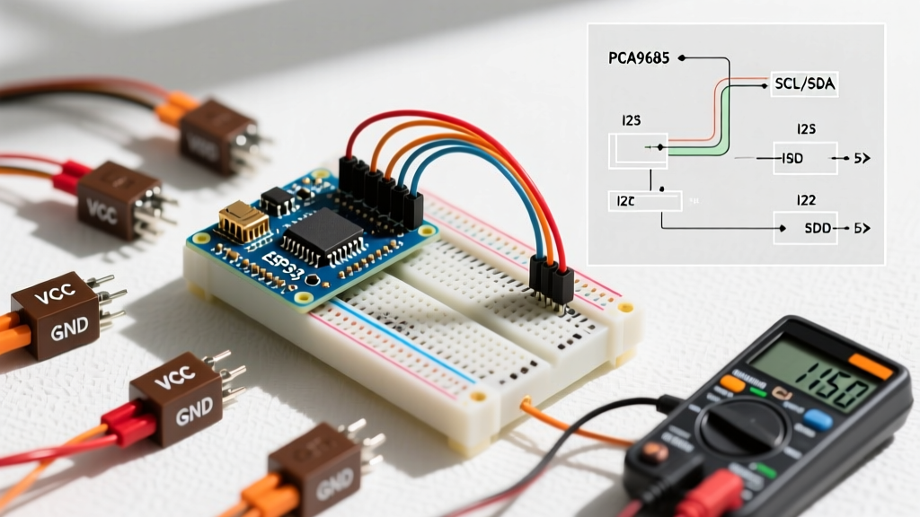
I2C Bus Optimization (BME280 / MS5611)
According to the official Arduino I2C documentation, the internal pull-up resistors on ATmega328P and ESP32 microcontrollers (often 20kΩ to 50kΩ) are far too weak for high-speed sensor polling. Weak pull-ups cause rounded signal edges, leading to bit-flipping in the least significant bits (LSBs) of the pressure registers.
- 100 kHz Standard Mode: Use 4.7kΩ external pull-up resistors on SDA and SCL lines to VCC.
- 400 kHz Fast Mode: Drop to 2.2kΩ pull-ups to overcome bus capacitance, especially if your I2C traces exceed 15 cm.
Analog Signal Conditioning (MPX5010DP)
The MPX5010DP outputs a ratiometric analog voltage. If you are powering the Arduino via USB, the 5V rail is notoriously noisy (often fluctuating between 4.75V and 5.15V). Because the sensor output is a ratio of VCC, this USB noise injects directly into your pressure readings.
The Fix: Do not use the default 5V reference. Connect the Arduino's 3.3V pin to the AREF pin, and use analogReference(EXTERNAL) in your setup. Then, use a precision voltage divider to scale the MPX5010DP's 0-5V output down to 0-3.3V. This bypasses the noisy USB power rail entirely.
Phase 3: The Two-Point Calibration Mathematics
Factory trimming handles the internal MEMS element, but system-level integration introduces PCB stress and soldering thermal shock, which shifts the baseline. We use a linear two-point calibration model: P_actual = (P_raw × Gain) + Offset.
Step-by-Step Calibration Routine
- Point 1 (Zero/Low): Expose the sensor to a known low pressure (e.g., 0 Pa differential for MPX5010DP, or current METAR station pressure for BME280). Record 100 samples and average them to establish
Raw_Low. - Point 2 (Span/High): Apply a known high pressure (e.g., 2500 Pa via manometer). Record 100 samples to establish
Raw_High. - Calculate Gain:
Gain = (True_High - True_Low) / (Raw_High - Raw_Low) - Calculate Offset:
Offset = True_Low - (Raw_Low × Gain)
Store these Gain and Offset variables in the Arduino's EEPROM so they persist across power cycles.
Phase 4: Environmental Killers & Thermal Drift
Air is rarely static or perfectly dry. Environmental factors will degrade your calibration over time if not mitigated.
As detailed in the Bosch Sensortec BME280 engineering documentation, rapid changes in ambient humidity can cause temporary hygroscopic swelling in the sensor's MEMS cavity, leading to pressure drift. Furthermore, if you are routing air through pneumatic tubes to a remote sensor, moisture condensation inside the tube will block the static pressure port, causing a massive lag in response time.
- Moisture Trap: Always install a small inline desiccant chamber (silica gel) before the air enters the sensor port.
- Thermal Isolation: If mounting the sensor on a PCB with a voltage regulator or WiFi module (like an ESP32), cut a physical slot in the PCB beneath the sensor to prevent thermal conduction from skewing the temperature compensation algorithm.
- IIR Filtering: For barometric sensors, enable the internal Infinite Impulse Response (IIR) filter via the sensor's configuration registers (e.g., setting the IIR coefficient to 16). This mechanically smooths out acoustic noise and wind gusts without requiring heavy software averaging.
Troubleshooting Common Accuracy Failures
| Symptom | Probable Root Cause | Engineering Fix |
|---|---|---|
| Readings jump erratically by 2-5 hPa | I2C bus noise or missing pull-ups | Add 4.7kΩ pull-ups; reduce I2C clock to 100kHz; check wire length. |
| Steady offset of exactly 10-20 hPa | Confusing Sea-Level (QNH) with Station Pressure | Recalibrate using raw METAR Station Pressure, not Altimeter setting. |
| Slow drift over 24 hours | Thermal coupling to MCU or humidity ingress | Slot the PCB for thermal isolation; add inline silica gel desiccant. |
| MPX5010DP reads high at zero pressure | Mechanical stress on solder joints or tubing | Reflow sensor pins; ensure pneumatic tubing is not pulling on the port. |
Summary
Achieving true accuracy with an Arduino pressure sensor for air applications requires moving beyond plug-and-play libraries. By establishing a verified METAR or manometer ground truth, conditioning your I2C or analog hardware, and applying a rigorous two-point mathematical calibration, you can elevate a $5 hobbyist sensor into a reliable, precision measurement tool capable of rivaling commercial industrial equipment.