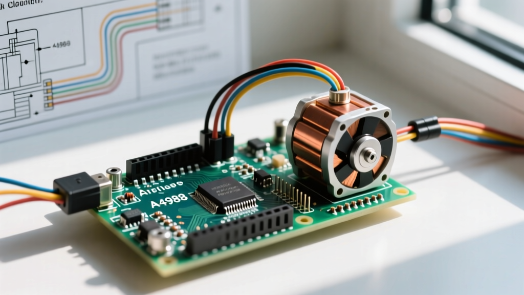

The "Humming but Not Moving" Phenomenon
There are few things more frustrating in DIY electronics than uploading your code, watching the Arduino's TX/RX LEDs blink, and hearing your NEMA 17 stepper motor emit a high-pitched hum without rotating a single degree. When you are trying to build a CNC plotter, a camera slider, or a robotic arm, a stalled motor brings the entire project to a halt.
As of 2026, while advanced silent drivers like the Trinamic TMC2209 have become standard in commercial 3D printers, the Allegro A4988 and Texas Instruments DRV8825 remain the undisputed champions of DIY Arduino projects due to their low cost (typically $2 to $5 per module). However, their simplicity masks complex underlying physics. According to Adafruit's comprehensive guide on stepper motors, a stepper motor is essentially a synchronous AC motor, and driving it requires precise synchronization of current, voltage, and timing.
If your Arduino drive stepper motor setup is failing, the issue almost always falls into one of four categories: current calibration, coil wiring, logic voltage mismatch, or pulse timing. This guide will walk you through a systematic, multimeter-in-hand diagnostic process to get your motor spinning smoothly.
Phase 1: Power Delivery and VREF Calibration
The most common reason a stepper motor vibrates in place or skips steps is incorrect current limiting. Stepper drivers like the A4988 use a sense resistor to monitor current and chop the voltage to prevent the motor coils from melting. If the reference voltage (VREF) is set too low, the motor lacks the torque to overcome its own internal detent torque. If set too high, the driver chip will overheat and trigger its internal thermal shutdown, resulting in intermittent stalling.
How to Measure and Set VREF
- Power the Logic, Not the Motor: Connect your Arduino to your PC via USB to power the driver's logic side (VDD). Do not connect the high-voltage motor power supply (VMOT) yet.
- Set Your Multimeter: Switch your digital multimeter to DC Voltage, 2V range.
- Probe the Potentiometer: Place the black probe on the driver's GND pin and the red probe gently on the metal shaft of the tiny trim potentiometer.
- Calculate Your Target: The formula varies by driver IC. For a standard A4988 with a 0.1Ω sense resistor, the formula is
VREF = Imax × 8 × Rsense. If your NEMA 17 (e.g., the popular 17HS4401) is rated for 1.5A per phase, your target VREF is1.5 × 8 × 0.1 = 1.2V. - Adjust Carefully: Using a ceramic screwdriver (metal shafts can short the wiper to nearby components and fry the chip), turn the potentiometer clockwise to increase voltage, or counter-clockwise to decrease it.
⚠️ The Golden Rule of Stepper Drivers: Never disconnect or reconnect the stepper motor wires while the driver is powered on. The RepRap Wiki explicitly warns that breaking the coil circuit while current is flowing causes a massive inductive voltage spike that will instantly blow the driver's internal MOSFETs, permanently destroying the module.
Phase 2: Coil Pair Identification and Polarity
Bipolar stepper motors have four wires, representing two distinct electromagnetic coils (Coil A and Coil B). If you wire one wire from Coil A and one from Coil B into the same driver output pair, the magnetic fields will fight each other, locking the rotor in place and causing the driver to overheat rapidly.
The "Shorting" Trick for Unknown Pinouts
If you lost the datasheet for your specific NEMA 17 or NEMA 23 motor, you can identify the coil pairs using basic physics:
- Leave all four motor wires disconnected from the driver.
- Spin the motor shaft with your fingers. Note the smooth, slightly detented resistance.
- Take two random wires and touch their bare ends together, shorting them.
- Spin the shaft again. If the shaft suddenly becomes very difficult to turn (due to the generated back-EMF creating a braking force), you have found a matching coil pair. Label them A1 and A2.
- The remaining two wires are your second coil pair (B1 and B2).
Polarity Note: If the motor spins in the wrong direction, you do not need to rewire the entire harness. Simply swap the two wires of one coil pair (e.g., swap A1 and A2) at the driver terminal.
Phase 3: Hardware Comparison and Failure Modes
Not all drivers behave identically. Upgrading your driver IC can often solve persistent torque or noise issues. Below is a 2026 market comparison of the most common DIY stepper drivers used with Arduino microcontrollers.
| Driver IC | Avg. Price (2026) | Max Continuous Current | Microstepping | Common Failure Mode & Quirks |
|---|---|---|---|---|
| Allegro A4988 | $2.50 - $3.50 | 1.0A (w/o heatsink) | Up to 1/16 | Loud at low speeds; VREF drifts as the board heats up. |
| TI DRV8825 | $3.50 - $5.00 | 1.5A (w/o heatsink) | Up to 1/32 | Requires longer step pulse widths (1.9µs); prone to audible high-frequency whine. |
| Trinamic TMC2209 | $8.00 - $12.00 | 2.0A (UART configurable) | Up to 1/256 | UART pin misconfiguration; StealthChop2 can cause slight positional lag in high-inertia CNCs. |
Phase 4: Logic Voltage and Signal Integrity
A frequent point of failure occurs when makers migrate from a 5V Arduino Uno (ATmega328P) to a 3.3V board like the Arduino Due, ESP32, or Teensy 4.1, while keeping their existing motor shields.
The A4988 and DRV8825 datasheets specify a logic high threshold (VIH) of typically 2.5V, but up to 3.15V depending on temperature and manufacturing tolerance. A 3.3V microcontroller outputting a logic HIGH might only measure 3.1V at the driver pin due to trace resistance and voltage drop. This puts the signal right on the edge of the driver's threshold, resulting in missed steps or complete unresponsiveness.
The Fix: If you are using a 3.3V Arduino-compatible board, you must either use a logic level shifter (like a CD4050 or TXS0108E) on the STEP and DIR lines, or upgrade to a modern driver like the TMC2209, which features 3.3V-tolerant logic inputs and operates flawlessly with modern ARM-based microcontrollers. You can find detailed wiring schematics for level shifting on the Pololu A4988 product page, which remains an authoritative reference for breakout board tolerances.
Phase 5: Software Timing and Mid-Band Resonance
If your hardware checks out but the motor still stalls at specific speeds, you are likely encountering software timing limits or mechanical resonance.
Minimum Pulse Width Violations
Stepper drivers require the STEP pin to be held HIGH for a minimum duration to register a step. The A4988 requires a minimum 1µs pulse, while the DRV8825 requires 1.9µs. If you are using a fast microcontroller and generating step pulses using direct port manipulation or tight `delayMicroseconds(1)` loops, interrupt service routines (ISRs) for serial communication or encoders can stretch or compress these pulses, causing the driver to ignore them.
Solution: Always use hardware-timer-based libraries like AccelStepper or MobaTools. These libraries handle pulse timing in the background, ensuring the minimum pulse width is strictly respected regardless of what your main `loop()` is doing.
The Mid-Band Resonance Deadzone
Stepper motors suffer from a well-documented physical phenomenon called mid-band resonance, typically occurring between 150 and 300 RPM. At these speeds, the rotor's inertia causes it to overshoot the magnetic pole, resulting in a severe drop in torque—sometimes down to zero. If your motor accelerates through this zone too slowly, it will stall and vibrate violently.
- Software Fix: Increase your acceleration rate in the
AccelStepperlibrary (e.g.,stepper.setAcceleration(2000);) so the motor punches through the resonance zone quickly before it can lose synchronicity. - Hardware Fix: Enable microstepping (1/8 or 1/16). Microstepping smooths the current sine wave delivered to the coils, drastically reducing the low-frequency harmonic vibrations that cause mid-band resonance.
- Mechanical Fix: Add a physical vibration damper to the rear shaft of the motor, or increase the mechanical load (inertia) of the system, which paradoxically stabilizes the rotor at resonant frequencies.
Summary Checklist for a Stalled Motor
Before replacing any components, run through this final diagnostic checklist:
- Is the 100µF decoupling capacitor soldered directly across VMOT and GND? (Without it, voltage spikes will reset the driver logic).
- Is the VREF calibrated to exactly 70% of the motor's rated RMS current?
- Are the coil pairs correctly identified and not mixed between the A and B outputs?
- Is the STEP pulse width meeting the minimum microsecond requirement for your specific driver IC?
By methodically isolating power, wiring, logic, and timing, you can transform a stalled, humming NEMA 17 into a precision motion control system capable of driving everything from 3D printer extruders to heavy-duty CNC router axes.