
Understanding Hall Effect Physics for Microcontrollers
Integrating a hall sensor Arduino circuit is a foundational skill for robotics, BLDC motor commutation, and precision RPM counting. At its core, a Hall effect sensor relies on the Lorentz force: when a current-carrying conductor is placed in a magnetic field, charge carriers are deflected, creating a measurable transverse voltage. For DIY electronics and industrial prototyping in 2026, translating this microvolt-level shift into a clean 5V or 3.3V logic signal requires understanding the distinct architectures of digital versus linear Hall ICs.
According to Texas Instruments' magnetic sensing guidelines, selecting the correct sensor topology prevents the most common integration failures: magnetic saturation, thermal drift, and electromagnetic interference (EMI). This tutorial dissects the two most ubiquitous sensors in the maker ecosystem—the A3144 digital switch and the SS49E linear sensor—and provides production-grade wiring and code implementations.
Digital vs. Linear: Selecting the Right Sensor Architecture
Before wiring your breadboard, you must match the sensor's output profile to your microcontroller's input capabilities. Digital sensors act as binary switches triggered by a specific magnetic flux density threshold, while linear sensors output a continuous voltage proportional to the magnetic field strength.
| Model Number | Type | Output Style | Activation Polarity | Typical Price (2026) |
|---|---|---|---|---|
| Allegro A3144 | Digital (Unipolar) | Open-Drain (Logic Low) | South Pole Only | $0.10 - $0.15 |
| Honeywell SS49E | Linear / Analog | Ratiometric Voltage | Both (Push/Pull) | $0.85 - $1.20 |
| TI DRV5053 | Linear / PWM | Analog or PWM | Configurable | $0.40 - $0.60 |
Hardware Integration: Wiring the A3144 Digital Sensor
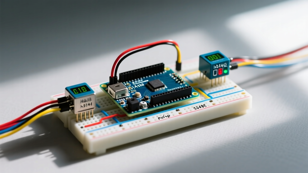
The A3144 is the workhorse for RPM encoders and limit switches. However, its internal schematic features an open-drain N-channel MOSFET output. This means the sensor can pull the signal line to Ground (LOW), but it cannot drive it HIGH. Beginners frequently wire the A3144 directly to an Arduino input and read floating garbage values because they omit the pull-up resistor.
The Pull-Up Resistor Requirement
To interface the A3144 with an Arduino Uno R4 Minima or Nano ESP32, you must pull the output line to VCC. While the internal AVR/ESP32 pull-ups (typically 20kΩ to 50kΩ) can work, they are highly susceptible to noise in electrically noisy environments like CNC routers or 3D printers. We recommend an external 4.7kΩ or 10kΩ metal film resistor connected between the sensor's OUT pin and the 5V rail.
Critical Polarity Warning: The A3144 is a unipolar sensor that specifically reacts to a South magnetic pole. If you test your circuit with the North pole of a neodymium magnet, the sensor will not trigger, leading to false hardware failure diagnoses. Always mark your magnet poles using a compass or a known reference sensor.
A3144 Pinout and Wiring Matrix
- Pin 1 (VCC): Connect to Arduino 5V. (Note: Do not exceed 24V, though 5V is optimal for logic matching).
- Pin 2 (GND): Connect to Arduino GND.
- Pin 3 (OUT): Connect to Arduino Digital Pin 2 (Hardware Interrupt 0). Place a 10kΩ resistor between Pin 3 and 5V.
Interrupt-Driven Arduino Code for RPM Measurement
Polling a digital Hall sensor inside the loop() function using digitalRead() is a critical anti-pattern. If the magnet passes quickly (e.g., a motor spinning at 10,000 RPM), the pulse width may be only a few microseconds, easily missing the polling window. Instead, we use hardware interrupts. The official Arduino attachInterrupt() documentation details how this maps physical pins to interrupt vectors.
// Hall Sensor Arduino RPM Counter (A3144)
const byte interruptPin = 2; // Hardware interrupt pin
volatile unsigned long lastPulseMicros = 0;
volatile unsigned long pulseInterval = 0;
volatile int pulseCount = 0;

void setup() {
  Serial.begin(115200);
  pinMode(interruptPin, INPUT_PULLUP); // Fallback internal pull-up
  // Attach interrupt on FALLING edge (when A3144 pulls line to GND)
  attachInterrupt(digitalPinToInterrupt(interruptPin), magnetDetected, FALLING);
}

void loop() {
  // Safely read volatile variables by disabling interrupts momentarily
  noInterrupts();
  unsigned long intervalCopy = pulseInterval;
  int countCopy = pulseCount;
  pulseCount = 0; // Reset for next window
  interrupts();

  if (intervalCopy > 0) {
    // Calculate RPM: (60 seconds * 1,000,000 microseconds) / (interval * pulses per rev)
    float rpm = (60.0 * 1000000.0) / (float)(intervalCopy * countCopy);
    Serial.print("Calculated RPM: ");
    Serial.println(rpm, 2);
  }
  delay(250); // Update display 4x per second
}

void magnetDetected() {
  unsigned long currentMicros = micros();
  // Simple software debounce (ignore bounces under 1000 microseconds)
  if (currentMicros - lastPulseMicros > 1000) {
    pulseInterval = currentMicros - lastPulseMicros;
    lastPulseMicros = currentMicros;
    pulseCount++;
  }
}
Analog Position Tracking with the SS49E Linear Sensor
When your project requires measuring continuous linear displacement—such as throttle position in a DIY electric skateboard or fluid level sensing via a magnetic float—the SS49E linear Hall sensor is required. According to Honeywell's sensing application notes, the SS49E provides a ratiometric analog output. At zero magnetic flux (0 Gauss), the output sits exactly at VCC / 2 (typically 2.5V). As a South pole approaches, voltage increases toward 5V; as a North pole approaches, it decreases toward 0V.
Handling Ratiometric Drift and ADC Resolution
Because the SS49E is ratiometric, its neutral point shifts if your Arduino's 5V rail sags to 4.8V under load. The neutral point drops from 2.5V to 2.4V. If you are using a classic Arduino Uno R3 with a 10-bit ADC (1024 steps), this 0.1V shift equates to a ~20-point error in your analogRead() data.
2026 Pro-Tip: Upgrade to the Arduino Uno R4 Minima. Its 14-bit ADC (16,384 steps) provides 16x the resolution, allowing you to resolve sub-millimeter magnetic field variations that the older R3 simply averages out.
Advanced Troubleshooting: EMI, Bounce, and Magnetic Saturation
In real-world deployments, Hall sensors rarely exist in a vacuum. They are mounted near stepper motors, switching power supplies, and relays. Here is how to engineer out the noise:
- High-Frequency EMI Filtering: Stepper motor drivers (like the TMC2209) emit massive high-frequency switching noise. You must place a 100nF (0.1µF) X7R ceramic bypass capacitor directly across the VCC and GND pins of the Hall sensor. The capacitor must be physically located within 2mm of the sensor's epoxy body to minimize trace inductance.
- Wiring Topology: If your sensor is mounted more than 15cm away from the Arduino, do not use standard Dupont jumper wires. Use a twisted pair cable (like CAT5e Ethernet wire) for the Signal and GND lines. Twisting the wires ensures that induced magnetic noise cancels itself out via common-mode rejection.
- Magnetic Saturation: The SS49E saturates at approximately ±600 Gauss. If you place an N52 neodymium magnet directly against the sensor face, the internal op-amp will rail out, and you will lose all linear tracking ability. Maintain an air gap of at least 5mm to 10mm, or use a weaker ceramic ferrite magnet for close-proximity sensing.
Frequently Asked Questions
Can I power a 5V Hall sensor with the Arduino's 3.3V pin?
Yes, but with caveats. The A3144 has a wide operating voltage range (4.5V to 24V), so 3.3V is technically out of spec and may cause erratic triggering. However, modern alternatives like the TI DRV5012 are explicitly designed for 1.8V to 5.5V operation and are ideal for 3.3V boards like the ESP32 or Arduino Nano 33 IoT.
Why is my RPM reading exactly double the actual motor speed?
This usually occurs when using a ring magnet with alternating poles (North-South-North-South). If your code triggers on both the rising and falling edges, or if you have two magnets mounted 180 degrees apart but your code assumes one pulse per revolution, the math will skew. Ensure your physical magnet count matches the pulsesPerRevolution variable in your RPM formula.
Do Hall sensors suffer from thermal drift?
All semiconductor sensors experience thermal drift. The A3144's operate point (Bop) can drift by up to 15% between -20°C and 85°C. For precision applications in varying outdoor temperatures, utilize a latching Hall sensor (like the A3212) which requires alternating magnetic poles to toggle, drastically reducing temperature-induced false triggers.