
The Anatomy of an I2C OLED Display Arduino Sensor Dashboard
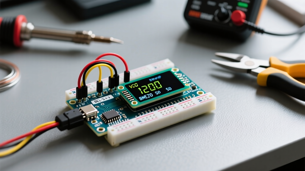
Integrating a visual interface into a microcontroller project transforms raw telemetry into actionable insights. In 2026, the OLED display Arduino ecosystem remains the gold standard for hobbyist and prosumer sensor dashboards. Unlike legacy 16x2 character LCDs that require bulky potentiometers and backlight inverters, modern I2C OLED modules offer pixel-addressable, high-contrast graphics with minimal wiring. This tutorial details the exact hardware selection, memory management strategies, and I2C bus conditioning required to build a flicker-free environmental monitoring dashboard using a 0.96-inch SSD1306 OLED and a BME280 sensor.
Hardware Bill of Materials (2026 Market Pricing)
When sourcing components, the market is saturated with both premium and generic clones. While generic modules are cost-effective, they often lack proper I2C pull-up resistors or voltage regulation.
- 0.96" SSD1306 I2C OLED (128x64): Generic clones average $4.50–$6.00, while premium boards like the Adafruit Monochrome OLED (PID 326) retail around $19.95. The premium boards include onboard 3.3V regulators and proper 4.7kΩ pull-up resistors.
- BME280 Environmental Sensor: Capable of reading temperature, humidity, and barometric pressure. Expect to pay $7.50–$9.00 for a 3.3V native breakout board.
- Microcontroller: The Arduino Uno R4 Minima ($18.00) is highly recommended over the legacy Uno R3 ($27.00) due to its 32KB SRAM and native 3.3V I2C logic tolerance.
Wiring Matrix and the 5V Logic Trap
A critical failure mode in OLED display Arduino projects is I2C bus voltage mismatch. The SSD1306 controller operates natively at 3.3V. If you are using a legacy 5V Arduino board, feeding 5V SDA/SCL signals directly into the OLED can degrade the internal I2C protection diodes over time, leading to intermittent bus lockups.
| Module Pin | Arduino Uno R4 Minima | Legacy 5V Uno R3 | Notes |
|---|---|---|---|
| VCC | 3.3V | 5V (Only if module has LDO) | Verify onboard regulator presence. |
| GND | GND | GND | Common ground is mandatory. |
| SCL | A5 (or dedicated SCL) | A5 (via Logic Level Converter) | BSS138 MOSFET recommended for 5V. |
| SDA | A4 (or dedicated SDA) | A4 (via Logic Level Converter) | Use 4.7kΩ pull-ups to 3.3V. |
Pro-Tip: According to the Arduino Wire Library Reference, the I2C bus requires pull-up resistors to function. Most generic OLEDs omit these to save $0.02 per unit. If your I2C scanner returns no devices, solder two 4.7kΩ resistors between the SDA/SCL lines and the 3.3V rail.
The SRAM Bottleneck: Memory Constraints Explained
Rendering a 128x64 pixel monochrome display requires a framebuffer. The math is straightforward: 128 columns × 64 rows / 8 bits per byte = 1,024 bytes of SRAM.
If you are using an older ATmega328P-based board with only 2,048 bytes of total SRAM, the display buffer consumes exactly 50% of your available memory. Once you add the BME280 sensor libraries, string variables for formatting, and the Wire library's internal 32-byte I2C buffers, you will experience stack collisions and random reboots.
The 2026 Solution: Migrate to the Arduino Uno R4 (Renesas RA4M1) or an ESP32-C3. These modern microcontrollers offer 32KB to 400KB of SRAM, rendering the 1KB display buffer completely negligible and allowing for complex sensor averaging algorithms without memory anxiety.
Library Showdown: Adafruit vs. U8g2
Choosing the right rendering engine dictates your project's performance and memory footprint. As detailed in the U8g2 Library Documentation, different rendering strategies yield vastly different results.
1. Adafruit_SSD1306 + Adafruit_GFX
- Pros: Extremely beginner-friendly, massive community support, simple coordinate-based drawing primitives.
- Cons: Allocates the full 1,024-byte buffer statically. Updating a single digit (like a temperature change) requires clearing and redrawing the entire screen, causing a noticeable 60Hz flicker.
2. U8g2 (Full vs. Partial Buffer)
- Pros: Supports hundreds of display controllers, includes advanced font rendering (including UTF-8 icons for temperature/humidity), and offers partial buffer modes.
- Cons: Steeper learning curve, uses a loop-based rendering structure (
u8g2.firstPage() / nextPage()) that confuses beginners.
Step-by-Step: Implementing Flicker-Free Partial Updates
Sensor data typically updates every 1 to 5 seconds. Redrawing the entire 128x64 grid every second causes eye fatigue and accelerates OLED phosphor burn-in. To achieve a flicker-free dashboard, you must isolate the redraw area.
If using the Adafruit ecosystem, avoid display.clearDisplay() on every loop iteration. Instead, draw a filled black rectangle strictly over the bounding box of the changing text before printing the new sensor value.
// Bounding box clear method to prevent global flicker

display.fillRect(64, 10, 64, 16, SSD1306_BLACK);
display.setCursor(64, 10);
display.print(bme.readTemperature(), 1);
display.display();
For advanced users, the Adafruit Monochrome OLED Breakouts guide suggests utilizing hardware I2C clock speeds. By default, the Arduino Wire library runs at 100kHz. You can safely push the SSD1306 I2C bus to 400kHz (Fast Mode) by adding Wire.setClock(400000); in your setup() function. This halves the transmission time of the 1KB buffer, virtually eliminating screen flicker during full redraws.
Sharing the I2C Bus: Managing Address Clashes
When building a sensor dashboard, the OLED display and the BME280 sensor will share the same SDA and SCL lines. While the I2C protocol supports up to 127 devices, practical address collisions are a common headache. The SSD1306 typically hardcodes its address to either 0x3C or 0x3D (selectable via a microscopic resistor pad on the back of the PCB). The BME280 defaults to 0x76 or 0x77.
Because these addresses occupy different spectrums of the 7-bit I2C address space, they will not clash. However, if you add a second sensor—such as a TSL2591 light sensor (which defaults to 0x29) or a BH1750 lux meter (0x23)—you must ensure no two devices share the same hex address. Always run the standard Arduino I2C Scanner sketch before soldering your final dashboard enclosure. If an address conflict occurs, you must physically desolder and reflow the surface-mount address jumper on the sensor breakout board, a task that requires a hot air rework station and a steady hand.
Furthermore, consider I2C bus capacitance. Every module you daisy-chain adds parasitic capacitance to the SDA/SCL lines. If your total wire length exceeds 30 centimeters, or you have more than three modules on the bus, the standard 4.7kΩ pull-up resistors become too weak to pull the voltage high within the I2C clock cycle. In these edge cases, drop your pull-up resistor value to 2.2kΩ or reduce the I2C clock speed from 400kHz back to 100kHz to maintain signal integrity.
Advanced Troubleshooting Matrix
When your OLED display Arduino integration fails, the issue is rarely the screen itself; it is almost always I2C bus degradation or memory corruption. Use this diagnostic matrix to isolate the fault.
| Symptom | Root Cause | Hardware / Software Fix |
|---|---|---|
| Screen shows static "white noise" on boot | Floating I2C lines during MCU boot sequence causing the SSD1306 to latch into an undefined state. | Add 4.7kΩ pull-up resistors to SDA/SCL. Add a 100nF decoupling capacitor across VCC and GND. |
| I2C Scanner finds device at 0x3C, but code fails | Library initialized for 0x3D, or I2C address clash with another sensor. | Pass the exact address in initialization: display.begin(SSD1306_SWITCHCAPVCC, 0x3C); |
| Display freezes after 4-5 hours of operation | I2C bus lockup due to EMI from nearby relay modules or switching regulators. | Use shielded twisted pair for I2C lines. Implement a watchdog timer to reset the MCU on bus hang. |
| Faint horizontal lines or "ghosting" | OLED burn-in from static UI elements, or incorrect VCC voltage. | Implement a pixel-shift routine that moves the entire UI by 1 pixel every 10 minutes. |
Final Calibration
Integrating an OLED display into an Arduino sensor project elevates a basic data-logger into a standalone diagnostic tool. By respecting the 3.3V logic thresholds, managing your SRAM buffers intelligently, and utilizing bounding-box redraws, you ensure a professional, flicker-free dashboard that will operate reliably in the field for years to come.