
Building Your First Ultrasonic Sensor HC-SR04 Arduino Project
Interfacing distance measurement into your microcontroller projects is a fundamental skill in embedded electronics, and building an ultrasonic sensor HC-SR04 Arduino setup remains the most accessible entry point in 2026. Recognizable by its two silver mesh cylinders (the 40kHz acoustic transducers) and blue PCB, the HC-SR04 has been the backbone of DIY robotics, liquid level monitoring, and proximity alarms for over a decade.
While the hardware is remarkably cheap—typically retailing between $1.20 and $2.50 per unit on major electronics marketplaces—beginners frequently run into hidden traps. From frying 3.3V logic pins to dealing with acoustic multipath interference, this comprehensive guide moves beyond basic copy-paste tutorials. We will cover the underlying physics, safe wiring practices for modern microcontrollers, and professional-grade code implementation.
2026 Component Shopping List
- HC-SR04 Ultrasonic Module: $1.20 - $2.50 (Generic), $8.00+ (Pololu/Adafruit regulated alternatives)
- Microcontroller: Arduino Uno R4 Minima ($28.00) or Nano 33 IoT ($22.00)
- Resistors for Logic Level Shifting: 1kΩ and 2kΩ (or 10kΩ potentiometer) - $0.10
- Jumper Wires & Breadboard: $5.00
Technical Specifications and Physical Limitations
Before writing a single line of code, you must understand the physical boundaries of the hardware. The HC-SR04 operates by emitting an eight-cycle burst of 40kHz ultrasound and listening for the echo. By measuring the time-of-flight (ToF), the microcontroller calculates the distance.
| Parameter | Specification | Real-World Notes |
|---|---|---|
| Operating Voltage | 5V DC (4.5V - 5.5V) | Performance degrades heavily below 4.7V. |
| Operating Current | 15mA (Standby: 2mA) | Safe for most MCU 5V rails, but avoid powering 5+ sensors from one USB port. |
| Measuring Range | 2cm to 400cm | Accuracy drops significantly past 300cm. |
| Blind Zone | < 2cm | The receiver is "deaf" while the transmitter is ringing. |
| Beam Angle | ~15 degrees (Cone) | Will detect objects to the side, not just directly in front. |
| Trigger Pulse | 10µs TTL High | Must be held high for exactly 10 microseconds to initiate. |
The 3.3V Logic Trap: Wiring the Echo Pin Safely
The most common hardware mistake beginners make in 2026 is connecting the HC-SR04 Echo pin directly to a 3.3V microcontroller. Modern boards like the Arduino Nano 33 IoT, Raspberry Pi Pico, and ESP32 operate at 3.3V logic.
The HC-SR04 requires 5V to drive the ultrasonic transducers effectively. When the sensor detects an echo, it pulls the Echo pin HIGH to its VCC level (5V) for the duration of the pulse. If you wire this directly to a 3.3V GPIO pin, you will back-feed 5V into the microcontroller, potentially destroying the pin or the entire MCU.
The Voltage Divider Solution
To safely interface the 5V Echo signal with a 3.3V Arduino, you must use a simple resistor voltage divider.
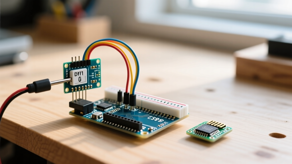
- Connect the HC-SR04 VCC to the Arduino 5V pin.
- Connect the HC-SR04 GND to the Arduino GND.
- Connect the HC-SR04 Trig pin directly to an Arduino digital pin (e.g., Pin 9). The 3.3V HIGH signal from the Arduino is usually sufficient to trigger the 5V module's logic threshold.
- Connect the HC-SR04 Echo pin to a 1kΩ resistor.
- Connect the other end of the 1kΩ resistor to an Arduino digital pin (e.g., Pin 10) AND to a 2kΩ resistor.
- Connect the other end of the 2kΩ resistor to GND.
Engineering Math: Using the voltage divider formula
Vout = Vin * (R2 / (R1 + R2)), we get5V * (2000 / (1000 + 2000)) = 3.33V. This safely steps the 5V pulse down to a 3.3V-tolerant level.
Writing the Code: Why You Should Ditch pulseIn()
Most basic tutorials use the native Arduino pulseIn() function to read the Echo pin. While functional, pulseIn() is a blocking function. It halts the entire microcontroller, waiting for the pulse to finish. If an object is 4 meters away, the sound wave takes roughly 23 milliseconds to return. In that time, your robot cannot read encoders, update motors, or check limit switches.
The professional standard is to use the NewPing library, which utilizes timer interrupts to measure the pulse in the background, keeping your main loop entirely non-blocking.
Optimized NewPing Implementation
#include <NewPing.h>

#define TRIGGER_PIN  9
#define ECHO_PIN     10
#define MAX_DISTANCE 400 // Maximum distance we want to ping (in cm)

// Initialize the NewPing object
NewPing sonar(TRIGGER_PIN, ECHO_PIN, MAX_DISTANCE);

void setup() {
  Serial.begin(115200);
}

void loop() {
  // Wait 50ms between pings (about 20 pings/sec). 29ms should be the shortest delay.
  delay(50);

  // ping_median() sends 5 pings and returns the median value, filtering out acoustic noise
  unsigned int uS = sonar.ping_median(5);

  Serial.print("Distance: ");
  if (uS == 0) {
    Serial.print("Out of range / Timeout");
  } else {
    Serial.print(sonar.convert_cm(uS));
    Serial.print("cm");
  }
  Serial.println();
}
Environmental Variables: Temperature and Acoustic Shadows
To achieve true E-E-A-T (Experience, Expertise, Authoritativeness, and Trustworthiness) in your sensor integration, you must account for the physics of sound. The HC-SR04 assumes a static speed of sound (roughly 343 meters per second). However, the speed of sound in air is highly dependent on temperature.
According to Georgia State University's HyperPhysics database, the speed of sound increases by approximately 0.606 m/s for every 1°C increase in temperature.
- At 20°C (Room Temp): Speed of sound is ~343 m/s.
- At 0°C (Freezing): Speed of sound drops to ~331 m/s.
If your Arduino robot operates in an unheated garage in winter, a true distance of 200cm will be calculated by the HC-SR04 as 207.3cm. That 7.3cm error could cause a collision. For high-precision outdoor or industrial applications, wire a DS18B20 waterproof temperature sensor to your Arduino and dynamically adjust the sonar.convert_cm() multiplier based on real-time temperature data.
Acoustic Shadows and Material Absorption
Ultrasonic sensors rely on sound reflection. Hard, flat surfaces (wood, metal, glass) reflect 40kHz waves beautifully. However, soft, porous materials like clothing, acoustic foam, or heavy curtains will absorb the acoustic energy, resulting in a false "Out of Range" reading. Furthermore, if an object is placed at a sharp angle (greater than 20 degrees relative to the sensor face), the sound wave will deflect away from the receiver, creating an "acoustic shadow."
For comprehensive data on how air density and humidity also marginally affect acoustic propagation, refer to the Engineering Toolbox's acoustic velocity charts.
Real-World Troubleshooting Matrix
| Symptom | Probable Cause | Actionable Fix |
|---|---|---|
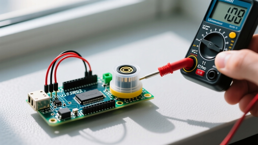
| Constant 0cm reading | Object inside the 2cm blind zone, or Echo pin not receiving 5V. | Move object back to 5cm. Check VCC with a multimeter; ensure it's not sagging below 4.7V. |
| Wildly fluctuating numbers (Jitter) | Multipath interference or electrical noise on the breadboard. | Use ping_median(5) in NewPing. Add a 100µF decoupling capacitor across the HC-SR04 VCC and GND pins. |
| Reads max distance (400cm) constantly | Trigger pulse is too short, or target material is sound-absorbent. | Verify delayMicroseconds(10) in manual code. Test against a hard, flat wooden board. |
| ESP32/Nano 33 IoT reboots randomly | 5V Echo pin back-feeding into 3.3V logic rail, triggering brownout reset. | Immediately disconnect. Implement the 1kΩ/2kΩ voltage divider on the Echo line. |
Frequently Asked Questions
Can I use multiple HC-SR04 sensors on one Arduino?
Yes, but do not fire them simultaneously. Ultrasonic sensors operating at the same 40kHz frequency will cause "crosstalk," where Sensor A reads the echo from Sensor B's ping. Use the NewPing ping_timer() method to fire them sequentially with at least a 35ms delay between each sensor to allow echoes to dissipate.
Is the HC-SR04 waterproof?
No. The standard blue HC-SR04 is an open-mesh design. Moisture, dust, and condensation will ruin the transducers. If you need liquid level sensing or outdoor use, look into sealed ultrasonic transducers or the JSN-SR04T, which features a waterproof, cabled probe head (typically costing around $6.00).
Why does my sensor get hot to the touch?
The HC-SR04 features a linear voltage regulator and analog driver ICs that generate heat during the high-current pulse emission. It is normal for the main IC to reach 40°C-50°C during continuous 20Hz pinging. Ensure adequate airflow if mounted inside a sealed 3D-printed enclosure.