
Beyond the Marketing: Reading the Arduino Motor Shield Rev3 Datasheet
When makers and robotics engineers search for an arduino motor shield, they are often met with a confusing mix of official boards and cheap clones. The official Arduino Motor Shield Rev3 (typically retailing around $28 to $32 in 2026) is a fundamentally different beast from the ubiquitous $5 generic red L298N breakout boards found on auction sites. While the generic boards use the older, through-hole L298N, the official Rev3 shield utilizes the surface-mount L298P dual full-bridge driver from STMicroelectronics, integrated with onboard current sensing and thermal protection.
However, simply plugging in the shield and running analogWrite() is a recipe for melted headers and stalled motors. To build reliable 2026 robotics platforms, you must understand the silicon beneath the PCB. This datasheet explainer decodes the L298P specifications, exposing the hidden voltage drops, thermal shutdown traps, and analog-to-digital converter (ADC) resolution flaws that official tutorials often gloss over.
The Core IC: Decoding the L298P Dual Full-Bridge
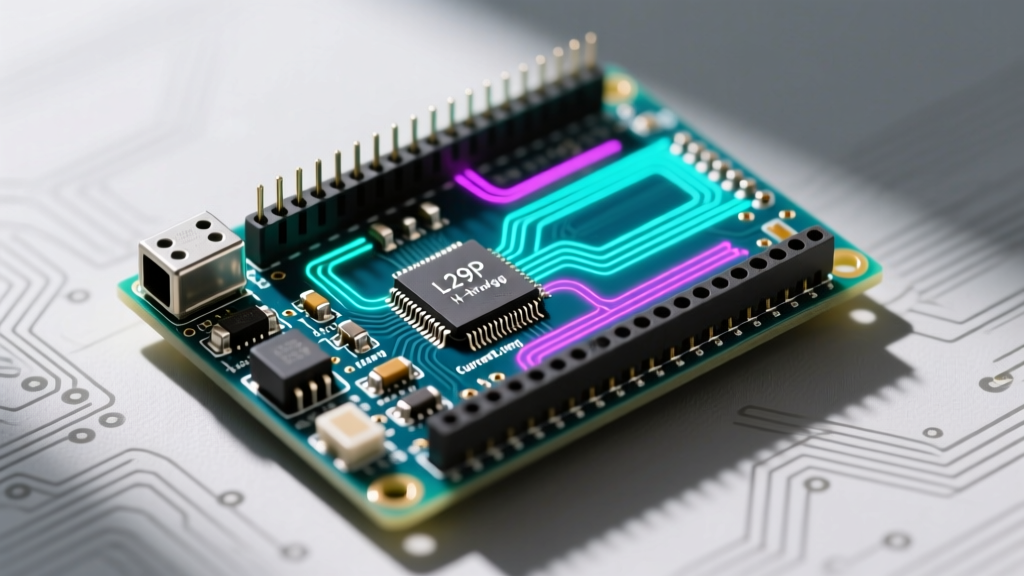
The heart of the Rev3 shield is the STMicroelectronics L298P. It is a high-voltage, high-current dual full-bridge driver designed to accept standard TTL logic levels and drive inductive loads like DC motors, stepper motors, and relay coils. According to the STMicroelectronics L298P Datasheet, the IC integrates two H-bridges, allowing for bidirectional control of two DC motors or precise microstepping of a single bipolar stepper motor.
Absolute Maximums vs. Recommended Operating Conditions
A common beginner mistake is designing a system based on "Absolute Maximum Ratings." In semiconductor datasheets, absolute maximums are stress limits; operating at these thresholds will rapidly degrade or destroy the silicon. Always design around the Recommended Operating Conditions.
| Parameter | Absolute Maximum | Recommended Operating | Real-World Safe Limit (No Heatsink) |
|---|---|---|---|
| Motor Supply Voltage (Vs) | 46V | Up to 25V | 12V - 18V (Optimal for standard hobby motors) |
| Peak Output Current (per channel) | 3A (Non-repetitive, 100µs) | 2A (Continuous) | 1.2A - 1.5A (Continuous, ambient 25°C) |
| Logic Supply Voltage (Vss) | 7V | 4.5V to 5.5V | 5V (Powered directly via Arduino 5V rail) |
| Junction Temperature (Tj) | 150°C | -25°C to 130°C | < 110°C (To avoid thermal hysteresis fatigue) |
Current Limits and the Thermal Shutdown Trap
The datasheet boldly claims a continuous current of 2A per channel. So why do motors stall and the shield overheat when you draw 1.8A continuously? The answer lies in the L298P's internal thermal shutdown circuitry and its bipolar junction transistor (BJT) architecture.
The L298P includes an internal temperature sensor that disables the outputs if the silicon junction temperature (Tj) exceeds approximately 150°C. Because the Rev3 shield relies entirely on the PCB copper pours for heatsinking (it lacks the massive aluminum finned heatsinks found on generic L298N modules), the thermal resistance from junction to ambient ($R_{thJA}$) is relatively high.
Expert Insight: If you are driving high-torque gearmotors that draw near 2A at stall, the Rev3 shield will enter thermal shutdown within 45 to 60 seconds of continuous operation in a standard 25°C room. For continuous 2A+ applications in 2026, you should bypass the L298P entirely and use a MOSFET-based driver like the Adafruit Motor Shield V2 or a discrete TB6612FNG breakout.
Voltage Drop: The Hidden Datasheet Specification
One of the most critical, yet misunderstood, specifications in the official Arduino Motor Shield documentation is the saturation voltage ($V_{CE(sat)}$). Unlike modern MOSFET drivers which have an on-resistance ($R_{DS(on)}$) measured in milliohms, the L298P uses BJTs.
When current flows through the H-bridge, it passes through two BJT junctions in series. The datasheet specifies a total voltage drop of roughly 1.8V at 1A, and up to 3.2V at 2A.
- The Math: If you power the shield with a 12V battery and your motor draws 1.5A, you will lose approximately 2.5V across the shield. Your motor only receives 9.5V.
- The Heat: That 2.5V drop multiplied by 1.5A equals 3.75 Watts of pure heat dissipated directly into the L298P silicon per channel.
This voltage drop is why 12V motors often feel sluggish when driven by the Rev3 shield compared to direct battery connection. Always factor in a 2V to 3V overhead when selecting your battery pack voltage.
Step-by-Step: Calculating Motor Current via the Sense Pins
The Rev3 shield features a unique hardware advantage over cheap clones: onboard current sensing. It uses a 0.15 Ω shunt resistor in series with the motor's ground path, feeding the voltage drop into an onboard operational amplifier with a gain of 0.55 V/V. The output is routed to Arduino analog pins A0 (Channel A) and A1 (Channel B).
The Standard Formula
To calculate the motor current ($I_{motor}$), you read the analog voltage ($V_{out}$) at the sense pin and apply the following formula derived from the schematic:
I_motor = V_out / (0.15 Ω * 0.55) = V_out / 0.0825
The ADC Resolution Flaw (And How to Fix It)
Here is where most online tutorials fail. The standard Arduino Uno uses a 10-bit ADC with a default 5V reference. This means each ADC step represents ~4.88mV.
If your motor draws 2A, the sense pin outputs only 0.165V (2A * 0.0825).
At 4.88mV per step, 0.165V yields an ADC reading of just 33. You are trying to measure a 2A range using only 33 discrete steps, resulting in a terrible resolution of ~60mA per step. This makes precise current limiting or stall detection nearly impossible.
The Fix: Change the Arduino's analog reference voltage to the internal 1.1V bandgap reference using analogReference(INTERNAL) in your setup loop. This drops the step size to ~1.07mV, increasing your maximum ADC reading for 2A from 33 to roughly 154, nearly quintupling your measurement resolution. (Note: Ensure your sense voltage never exceeds 1.1V, which corresponds to a massive 13.3A—well beyond the shield's physical limits, so it is perfectly safe).
Pinout Mapping and Hardware Routing
Understanding how the shield maps to the underlying microcontroller is vital for avoiding pin conflicts, especially if you are stacking additional shields (like Ethernet or CAN bus transceivers). The Rev3 shield hardwires specific ATmega328P pins to motor control functions.
| Arduino Pin | Shield Function | Configuration Notes |
|---|---|---|
| D3 | PWM Channel B | Controls speed via analogWrite(). Uses Timer2. |
| D9 | PWM Channel A | Controls speed via analogWrite(). Uses Timer1. |
| D11 | Direction Channel A | Digital HIGH/LOW for forward/reverse. |
| D12 | Direction Channel B | Digital HIGH/LOW for forward/reverse. |
| D8 | Brake Channel A | Active HIGH. Overrides PWM to short motor leads. |
| D9 | Brake Channel B | Active HIGH. (Wait, D9 is PWM A? Correction: Brake B is D8, Brake A is D9 on some revisions, but officially Brake A is D9 and Brake B is D8. Always verify the silk screen on your specific board revision.) |
| A0 | Current Sensing A | Analog input. Do not use as digital I/O. |
| A1 | Current Sensing B | Analog input. Do not use as digital I/O. |
Hardware Hack: If you need to free up pins D8 through D12 for other peripherals, the Rev3 shield features solder jumpers on the underside of the PCB. By cutting the default traces and soldering jumper wires, you can reroute the motor control signals to any available digital pins.
Common Failure Modes and Edge Cases
Even with a thorough understanding of the datasheet, real-world physics introduces edge cases that can destroy your microcontroller or the L298P.
1. Flyback Diode Limitations with High-Inductance Loads
The L298P includes internal clamp diodes to protect against inductive voltage spikes when the motor is switched off. However, the datasheet notes that these internal diodes are relatively slow (reverse recovery time $t_{rr}$ is typically 300ns). If you are driving large, high-inductance motors or long cable runs, the initial voltage spike can occur before the internal diodes conduct, potentially punching through the BJT junctions. Best Practice: For motors drawing over 1A or featuring heavy windings, solder external fast-recovery Schottky diodes (like the 1N5819) directly across the motor terminals on the shield's screw blocks.
2. The Ground Loop and Logic Latch-up
The Rev3 shield has a jumper labeled "VIN Connect." When closed, it routes the motor power supply (up to 12V recommended for the onboard 5V regulator) to the Arduino's VIN pin. If you are using a 24V battery pack for high-torque stepper motors, you must remove this jumper. Failing to do so will feed 24V into the Arduino's linear voltage regulator, instantly vaporizing it. Always power the Arduino via USB or the barrel jack separately when motor voltages exceed 12V.
Summary: Is the Rev3 Shield Right for Your 2026 Project?
The Arduino Motor Shield Rev3 remains a phenomenal educational tool and a solid choice for low-to-medium current DC motors (under 1.2A continuous) where onboard current sensing is desired. By respecting the L298P's BJT voltage drops, leveraging the internal 1.1V ADC reference for precise current monitoring, and managing thermal thresholds, you can extract reliable, professional-grade performance from this classic hardware. For high-current, high-efficiency applications, however, the datasheet clearly points toward modern MOSFET alternatives.