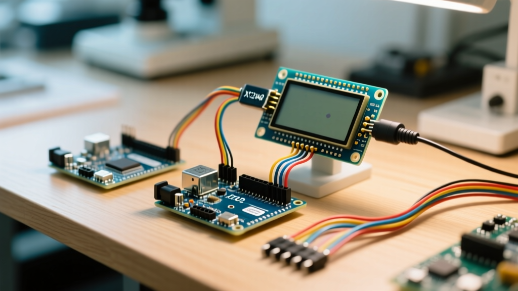

Building a Robust Display 7 Segment Arduino Interface
Building a robust display 7 segment arduino interface requires moving beyond basic tutorials and breadboard prototypes. In real-world applications—such as UV resin curing stations, darkroom exposure timers, or industrial batch counters—reliability, non-blocking code architecture, and signal integrity are non-negotiable. While raw shift registers like the 74HC595 can drive 7-segment displays, they consume excessive GPIO pins and require constant microcontroller-level multiplexing, which drains processing cycles.
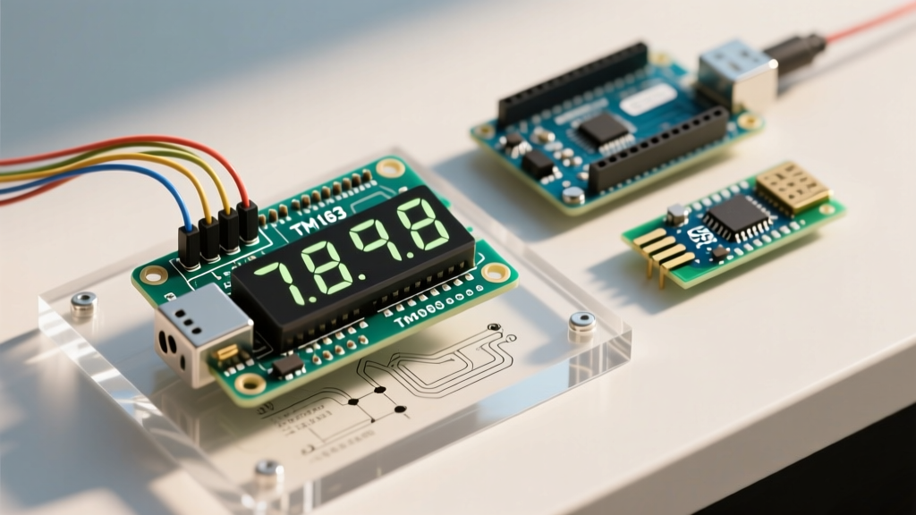
This is where the TM1637 LED driver chip shines. By handling multiplexing and brightness control internally, the TM1637 frees your microcontroller to focus on core logic. In this guide, we will design a high-precision, non-blocking countdown timer using an Arduino Uno R4 Minima and a 4-digit TM1637 module, addressing the exact hardware edge cases and software pitfalls that cause field failures in commercial deployments.
Hardware BOM and 2026 Cost Analysis
For a commercial or heavy-duty DIY build, component selection impacts both budget and longevity. As of 2026, the Arduino Uno R4 Minima offers a 48 MHz Arm Cortex-M4 processor, providing ample overhead for complex timing tasks without the legacy bottlenecks of the older ATmega328P.
| Component | Model / Specification | Estimated Cost (USD) | Role in Circuit |
|---|---|---|---|
| Microcontroller | Arduino Uno R4 Minima | $22.50 | Main logic and timing engine |
| Display Module | HiLetgo TM1637 4-Digit (0.56') | $3.50 | Visual output and digit multiplexing |
| Decoupling Capacitors | 100nF Ceramic + 100µF Electrolytic | $0.15 | Voltage stabilization and noise filtering |
| Pull-Up Resistors | 10kΩ Carbon Film (x2) | $0.05 | Bus stabilization for long wire runs |
| Wiring | 24 AWG Silicone Stranded Wire | $1.20 | Flexible, heat-resistant connections |
Total Prototype Cost: ~$27.40. For scaled PCB manufacturing, the TM1637 IC itself costs roughly $0.35 in bulk, making it highly economical for production runs.
Wiring Deep Dive: Signal Integrity and Logic Levels
A common failure mode in real-world deployments is signal degradation over distance. The TM1637 uses a proprietary 2-wire serial protocol that mimics I2C but lacks strict hardware acknowledgment. It relies on precise timing of the CLK (Clock) and DIO (Data I/O) lines.
Standard Short-Run Wiring (Under 30cm)
- VCC: Connect to 5V on the Arduino Uno R4 Minima.
- GND: Connect to system ground.
- CLK: Connect to Digital Pin 2.
- DIO: Connect to Digital Pin 3.
Long-Run Wiring (Up to 1.5 Meters)
If your display is mounted on an enclosure door while the Arduino remains on the backplate, wire capacitance will round off the sharp digital edges of the CLK signal, leading to ghosting or dropped digits. To combat this:
- Add 10kΩ pull-up resistors between the 5V rail and both the CLK and DIO lines at the display module end.
- Use twisted pair cable for the CLK and GND lines to minimize electromagnetic interference (EMI) from nearby AC relays or stepper motors.
- Solder a 100nF ceramic capacitor directly across the VCC and GND pins on the back of the TM1637 PCB. This provides instantaneous local current during LED multiplexing spikes, preventing brownouts that corrupt the chip's internal SRAM.
Non-Blocking Code Architecture
Beginners often use the delay() function to create timers. In a real-world application, blocking the main loop prevents the system from reading sensors, monitoring emergency stop buttons, or handling serial communication. We must use a non-blocking approach leveraging the Arduino millis() function to track elapsed time.
Below is the core logic utilizing the industry-standard TM1637Display library by Avishay Orpaz, which efficiently handles the low-level bit-banging required by the chip.
#include <TM1637Display.h>

#define CLK_PIN 2
#define DIO_PIN 3

TM1637Display display(CLK_PIN, DIO_PIN);

unsigned long previousMillis = 0;
const long interval = 1000;
int countdownSeconds = 300; // 5-minute UV resin cure time
bool timerActive = true;

void setup() {
  display.setBrightness(0x0a); // Set brightness to ~66% to reduce thermal load
  display.showNumberDecEx(countdownSeconds, 0b11100000, true);
}

void loop() {
  unsigned long currentMillis = millis();

  if (timerActive && (currentMillis - previousMillis >= interval)) {
    previousMillis = currentMillis;
    countdownSeconds--;

    if (countdownSeconds <= 0) {
      timerActive = false;
      display.showNumberDecEx(0, 0b11100000, true);
      triggerAlarm(); // Custom function for buzzer/relay
    } else {
      updateDisplay();
    }
  }

  // Add sensor reading or button polling logic here (non-blocking)
}

void updateDisplay() {
  int minutes = countdownSeconds / 60;
  int seconds = countdownSeconds % 60;
  int displayValue = (minutes * 100) + seconds;

  // 0b11100000 enables the colon separator
  display.showNumberDecEx(displayValue, 0b11100000, true);
}
Handling the millis() Rollover Edge Case
Notice the subtraction method used in the conditional: (currentMillis - previousMillis >= interval). This specific syntax is mathematically immune to the 32-bit integer rollover that occurs every 49.7 days. If your timer is deployed in an always-on industrial setting, using currentMillis >= previousMillis + interval will cause catastrophic failure when the microcontroller's internal clock wraps around to zero.
Field Troubleshooting: Ghosting, Flicker, and Dimming
Even with perfect code, hardware realities can degrade the display output. Here is a diagnostic matrix for common TM1637 anomalies encountered in the field.
| Symptom | Root Cause | Engineer's Solution |
|---|---|---|
| Ghosting (Faint segments) | Insufficient multiplexing dead-time or VCC sag. | Verify the 100nF decoupling cap is present. Lower brightness via code to reduce peak current draw. |
| Random Flickering | EMI injection on the CLK line from AC loads. | Route signal wires away from AC mains. Add 100pF ceramic capacitors from CLK/DIO to GND to filter high-frequency noise. |
| Display goes blank randomly | Internal SRAM corruption due to voltage brownout. | Add a 100µF bulk electrolytic capacitor at the power entry point of the enclosure. |
| Colon fails to blink | Incorrect bitmask passed to showNumberDecEx. | Ensure the second argument is exactly 0b11100000 (or 0b01000000 for specific module revisions). |
Pro-Tip for Enclosure Design: The standard red 7-segment displays bleed light heavily through the sides of the digits. When mounting behind an acrylic or 3D-printed PETG faceplate, apply a layer of black electrical tape or matte black paint to the sides of the LED module housing. This prevents internal reflections that make the display look 'washed out' in high-ambient-light environments.
Brightness Control and Thermal Management
The TM1637 supports 8 levels of pulse-width modulation (PWM) brightness, controlled via the setBrightness(level) method, where level ranges from 0 (1/16 pulse width) to 7 (14/16 pulse width). Additionally, passing a value like 0x08 to 0x0f maps to the same levels but ensures the display is turned ON (the 4th bit acts as the display enable flag).
In a sealed NEMA-rated enclosure, running a 4-digit display at maximum brightness (level 7) can draw upwards of 120mA, generating localized heat that affects nearby temperature sensors like the BME280. For indoor applications, setting the brightness to 0x0a (level 2, roughly 4/16 pulse width) provides excellent readability while cutting current consumption by over 60%, ensuring thermal stability for the rest of your peripheral stack.
Summary
Integrating a display 7 segment arduino setup using the TM1637 is a masterclass in offloading microcontroller resources. By respecting the physical limitations of the 2-wire bus, implementing proper decoupling capacitance, and strictly adhering to non-blocking timing architectures, you transform a $3 hobbyist component into a reliable, industrial-grade human-machine interface (HMI).