
Beyond the Basics: Decoding the Moisture Soil Sensor Arduino Datasheet
When integrating a moisture soil sensor Arduino builders frequently encounter a frustrating cycle: the system works perfectly on the workbench, but fails within three weeks of being deployed in a garden bed. This failure rarely stems from flawed microcontroller logic. Instead, it originates from a fundamental misunderstanding of the sensor's underlying electrical characteristics, analog degradation, and silicon-level limitations. In this datasheet explainer, we strip away the generic tutorial fluff and dive deep into the actual electrical specifications, failure modes, and calibration mathematics required to build a reliable soil monitoring peripheral in 2026.
The Hardware Reality: Resistive vs. Capacitive Architectures
Before analyzing the pinout, we must address the two dominant architectures available on the market. If your project relies on the traditional YL-69 resistive probe, you are working with obsolete technology. Resistive sensors pass a direct current through the soil between two exposed metal pads. This triggers galvanic corrosion, dissolving the metal into the soil and permanently altering the sensor's baseline resistance within days.
The modern standard for any serious moisture soil sensor Arduino project is the Capacitive Soil Moisture Sensor (v1.2 or v2.0). Instead of measuring resistance, this sensor measures the dielectric permittivity of the surrounding soil. Water has a dielectric constant of approximately 80, while dry soil sits between 3 and 5. The sensor's internal circuitry translates this capacitance change into an analog voltage output, completely isolating the electronics from the corrosive soil environment.
2026 Market Note: A standard 5-pack of YL-69 resistive sensors costs around $4.00, but they are effectively e-waste. A single high-quality Capacitive v2.0 sensor with factory-applied conformal coating retails for $3.50 to $5.00. Always choose capacitive for permanent deployments.
Datasheet Deep Dive: Pinout and Electrical Specifications
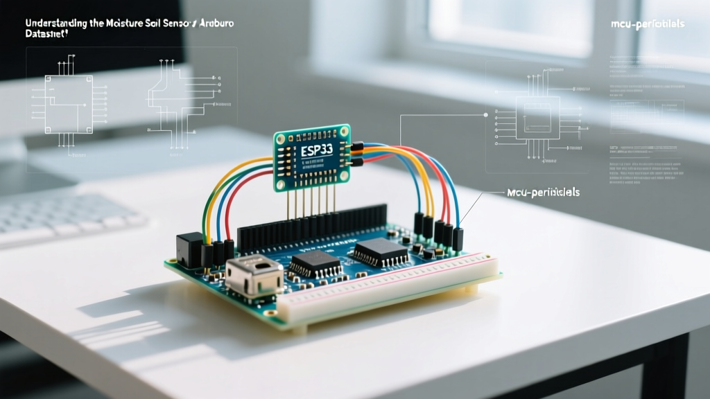
Whether you are using an Arduino Uno (ATmega328P) or an ESP32, understanding the breakout board's voltage regulation and logic levels is critical. Below is the definitive pinout and operational specification table for the standard capacitive sensor module.
| Pin Label | Function | Electrical Characteristics & Notes |
|---|---|---|
| VCC | Power Input | 3.3V to 5.5V. See the 'Silicon Flaws' section below regarding 5V operation on v1.2 boards. |
| GND | Ground | Common ground with the microcontroller. Essential for accurate ADC readings. |
| AO | Analog Output | Outputs a voltage inversely proportional to moisture. Wet soil yields lower voltage (approx 1.2V), dry soil yields higher voltage (approx 2.8V on a 3.3V supply). |
| DO | Digital Output | Driven by the LM393 comparator. Pull-up resistor required (usually populated on-board). Outputs LOW when moisture exceeds the potentiometer threshold. |
The LM393 Comparator and the Digital Output (DO)
The digital output (DO) pin is largely useless for precision agriculture, but understanding its datasheet is vital for basic irrigation triggers. The DO pin is controlled by an LM393 dual differential comparator. According to the Texas Instruments LM393 datasheet, this chip features an open-collector output. This means the LM393 can pull the DO pin to ground (LOW), but it cannot actively drive it HIGH. The breakout board includes a 10kΩ pull-up resistor tied to VCC to handle the HIGH state. When adjusting the blue trimpot on the board, you are altering the reference voltage fed into the LM393's inverting input, thereby setting the exact moisture threshold that triggers the digital interrupt.
Analog Output (AO) and ADC Calibration Mathematics
The true value of the moisture soil sensor Arduino integration lies in the Analog Output (AO) pin. The sensor outputs a continuous voltage that must be read by the microcontroller's Analog-to-Digital Converter (ADC).
When using a 5V Arduino Uno, the 10-bit ADC maps the 0-5V range to integer values between 0 and 1023. However, capacitive sensors are inversely proportional. As soil moisture increases, the capacitance increases, and the output voltage drops. Therefore, a higher ADC value means drier soil.
Step-by-Step Calibration Protocol
Do not rely on hardcoded values found in generic GitHub repositories. Soil composition (clay, loam, sand) drastically alters the dielectric baseline. You must perform a two-point calibration using the Arduino analogRead() function.
- Dry Baseline (Air): Hold the sensor in dry ambient air. Record the ADC value. For a 5V Arduino, this typically reads between
580and610. - Wet Baseline (Saturation): Submerge the sensor in a glass of water up to the marked maximum immersion line. Record the ADC value. This typically reads between
280and310. - Map the Values: Use the Arduino
map()function to translate these raw ADC readings into a 0-100% moisture scale.
// Calibration Variables based on physical testing
const int dryValue = 595;
const int wetValue = 290;

void setup() {
  Serial.begin(115200);
}

void loop() {
  int rawADC = analogRead(A0);
  // Note the inversion: dryValue maps to 0%, wetValue maps to 100%
  int moisturePercent = map(rawADC, dryValue, wetValue, 0, 100);

  // Constrain to prevent negative or >100% errors from sensor noise
  moisturePercent = constrain(moisturePercent, 0, 100);

  Serial.print("Moisture Level: ");
  Serial.print(moisturePercent);
  Serial.println("%");
  delay(2000);
}
Known Silicon Flaws and Edge Cases (v1.2 vs v2.0)
If you are reading this datasheet explainer to debug a failing system, you are likely encountering one of the well-documented manufacturing flaws inherent to early capacitive sensor revisions.
The v1.2 Voltage Regulator Dropout
The v1.2 capacitive sensor utilizes a cheap SMD voltage regulator to step down 5V to the 3.3V required by the internal 555 timer oscillator circuit. In many production batches, this regulator lacks adequate thermal dissipation. When powered continuously at 5V, the regulator overheats, causing the output voltage to droop. This manifests in your Arduino code as a slow, steady drift in the ADC baseline over 48 hours, making the soil appear artificially wetter than it is.
The Fix: If you must use a v1.2 board, bypass the onboard regulator entirely by powering the VCC pin directly with 3.3V from your Arduino or ESP32. This disables the faulty regulator and provides a stable, noise-free voltage to the oscillator.
The v2.0 Conformal Coating Improvement
Released to address the corrosion of the solder joints at the top of the probe, the v2.0 revision features a thicker PCB and a factory-applied epoxy conformal coating over the exposed copper traces. However, be aware that the dielectric constant of this epoxy coating slightly shifts the 'Dry Baseline' ADC value. Always recalibrate your dryValue variable when swapping between v1.2 and v2.0 hardware.
Long-Term Deployment: Power Cycling to Prevent Ion Migration
Even with capacitive sensing, leaving the sensor powered 24/7 in highly acidic or saline soils can cause slow ion migration and dielectric breakdown of the PCB mask. To maximize the lifespan of your moisture soil sensor Arduino deployment, do not wire the sensor directly to the constant 5V rail.
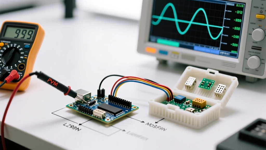
Instead, connect the sensor's VCC pin to a digital GPIO pin on your Arduino (or a MOSFET-controlled rail for ESP32 deep-sleep setups). Power the sensor only for the 50 milliseconds required to stabilize the capacitor and take the analogRead() measurement, then pull the GPIO LOW. This zero-power standby state eliminates continuous electrical stress, extending the operational lifespan of the peripheral from a single season to upwards of five years in harsh outdoor environments.
Summary of Best Practices
- Discard Resistive Probes: Upgrade to Capacitive v2.0 to eliminate galvanic corrosion.
- Power at 3.3V: Feed 3.3V directly to VCC to bypass the unreliable onboard regulators found on clone boards.
- Calibrate Per Soil Type: Use the two-point (air/water) calibration method to define your
map()constraints. - Implement Power Cycling: Drive the sensor VCC via a GPIO pin to prevent long-term dielectric degradation.