
The Problem with Toy Tutorials in Stepper Automation
If you have ever searched for stepper motor control with Arduino, you have likely encountered tutorials featuring the 28BYJ-48 stepper motor and a ULN2003 Darlington driver. While excellent for learning basic digital logic, these components are practically useless for real-world mechanical loads. The 28BYJ-48 suffers from severe gear backlash, low torque, and poor speed characteristics. When building a linear actuator, a CNC camera slider, or an automated dispensing rig in 2026, you need precision, high holding torque, and dynamic motion profiling.
To bridge the gap between blinking an LED and moving a 5-kilogram payload along a T8 lead screw with sub-millimeter accuracy, we must upgrade to industrial-standard hardware. This guide details the exact architecture required for robust stepper motor control with Arduino, focusing on the NEMA 17 form factor, modern UART-enabled silent drivers, and the physics of motion profiling.
Selecting Real-World Hardware for High-Torque Applications
For a linear actuator requiring high push/pull force, the NEMA 17 (specifically the 17HS4401 model) remains the undisputed workhorse of the DIY and prosumer automation space. The 17HS4401 delivers approximately 42 Ncm (Newton-centimeters) of holding torque and operates at a rated current of 1.5A per phase. As of 2026, you can source high-quality 17HS4401 motors from manufacturers like StepperOnline or BigTreeTech for roughly $12 to $15 USD.
However, the motor is only half the equation. The driver dictates the microstepping resolution, thermal efficiency, and acoustic noise. The ancient A4988 driver is now considered obsolete for precision builds due to its loud operation and poor microstepping decay control. Instead, we utilize the Trinamic TMC2209. The TMC2209 supports UART communication, allowing the Arduino to dynamically adjust current limits and enable 'StallGuard' for sensorless homing without requiring physical limit switches.
2026 Stepper Driver Comparison Matrix
| Driver IC | Max Current | Microstepping | Interface | Acoustic Noise | Real-World Verdict |
|---|---|---|---|---|---|
| A4988 | 2.0A | 1/16 | Step/Dir | High (Loud whine) | Legacy; avoid for new 2026 builds. |
| DRV8825 | 2.5A | 1/32 | Step/Dir | Medium | Better torque, but still noisy at low speeds. |
| TMC2209 | 2.8A (Peak) | 1/256 | Step/Dir + UART | Ultra-Low (StealthChop) | Industry standard for precision and silent operation. |
Power Delivery: Why 24V Beats 12V in Stepper Applications
A common failure mode in DIY linear actuators is a severe loss of torque at higher speeds. This is rarely a motor defect; it is a power supply voltage issue. Stepper motor windings possess high inductance. When the driver attempts to push current through the coils at high stepping rates, the inductance resists the rapid change in current. According to the physics outlined in the RepRap Stepper Motor documentation, increasing the supply voltage forces the current to reach its target level faster, thereby maintaining torque at higher RPMs.
For a 17HS4401 motor, do not use a 12V power supply. Instead, use a 24V 5A Mean Well LRS-120-24 enclosed power supply (approximately $25 USD). This provides 120 watts of continuous headroom, ensuring the driver has enough voltage overhead to maintain microstepping accuracy even when the actuator encounters unexpected friction on the lead screw.
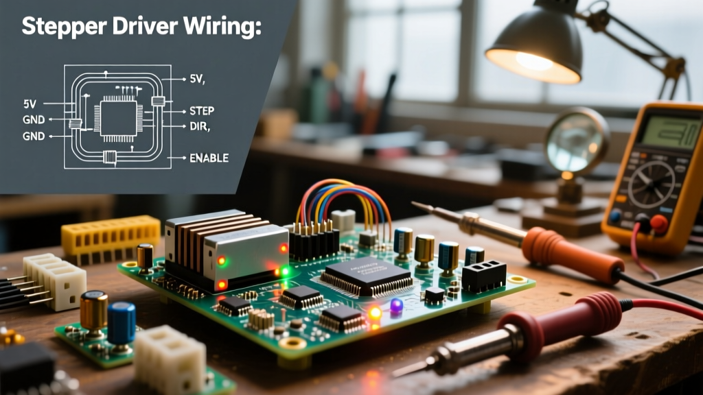
Wiring the TMC2209 to an Arduino Nano
Wiring a high-current stepper driver requires strict adherence to decoupling and flyback protection protocols. The TMC2209 is highly sensitive to voltage spikes generated by the motor's inductive kickback during rapid deceleration.
The Decoupling Capacitor Rule
You must solder a 100µF 35V low-ESR electrolytic capacitor directly across the VMOT and GND pins on the TMC2209 breakout board. This capacitor acts as a local energy reservoir, absorbing inductive voltage spikes that would otherwise destroy the driver's internal MOSFETs. For 24V systems, adding a bidirectional TVS (Transient Voltage Suppression) diode across the power rails is highly recommended for additional clamping protection.
UART Resistor Configuration
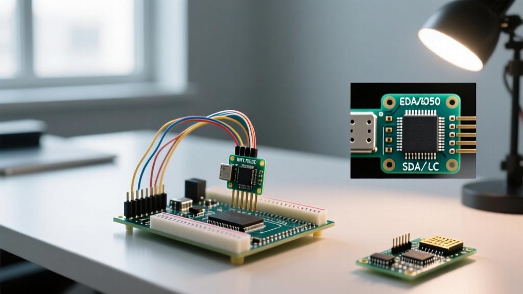
To enable dynamic current control via the Arduino, connect the TMC2209's TX/RX pins to the Arduino's hardware or software serial pins. Crucially, you must place a 1kΩ resistor in series with the TX line from the TMC2209 to the Arduino's RX pin. This prevents bus contention and protects the microcontroller's GPIO pins from back-feeding current.
Motion Profiling with AccelStepper
Never use basic digitalWrite() loops to pulse the STEP pin. Real-world mechanical systems have mass, and mass requires acceleration to overcome inertia. If you command a NEMA 17 motor to instantly jump from 0 to 1000 steps per second, the rotor will simply stall and vibrate, missing hundreds of steps.
We use the AccelStepper Library to generate trapezoidal motion profiles. By defining maximum speed and acceleration, the library calculates the exact microsecond delays between step pulses to smoothly ramp the motor up to speed and gracefully decelerate before reaching the target position.
Expert Insight on Inertia: When coupling a NEMA 17 to a T8x2 lead screw (2mm lead per revolution), the rotational inertia of the screw adds to the rotor's inertia. A safe starting acceleration value for this specific mechanical coupling is400 steps/sec^2. Pushing this past1500 steps/sec^2without a mechanical damper will almost certainly result in mid-band resonance and stalled motion.
Advanced UART Configuration for the TMC2209
One of the most powerful features of modern stepper motor control with Arduino is the ability to configure the driver on the fly via UART. Using the TMCStepper library alongside AccelStepper, you can initialize the driver parameters in your setup() loop.
- RMS Current Setting: Instead of turning a fragile physical potentiometer, you set the exact RMS current via code. For the 1.5A rated 17HS4401, setting the UART RMS current to
1.2Aprovides an excellent balance of torque and thermal management, keeping the motor case temperature around 50°C during continuous duty. - StealthChop vs. SpreadCycle: Enable StealthChop for slow, silent camera slider movements (under 200 RPM). For high-speed linear actuator retracts, switch to SpreadCycle via UART to prevent the motor from losing synchronization at high velocities.
- StallGuard Threshold (SGTHRS): By monitoring the TMC2209's diagnostic pin, the Arduino can detect when the motor stalls against a physical hardstop. This allows you to implement 'sensorless homing', eliminating the need for mechanical microswitches on your linear rail.
Troubleshooting Real-World Failure Modes
Even with perfect code, mechanical realities will test your system. Here is how to diagnose the most common field failures in 2026 stepper builds:
1. Mid-Band Resonance and Acoustic Howling
Symptom: The motor sounds like it is grinding or howling between 2 to 4 revolutions per second, and loses torque.
Cause: Stepper motors naturally exhibit a resonance frequency where the rotor overshoots the magnetic detent and oscillates.
Solution: If using the TMC2209, ensure StealthChop is enabled, as its PWM decay algorithm actively dampens this resonance. Mechanically, adding a silicone elastomer damper to the rear shaft of the NEMA 17 shifts the resonant frequency and absorbs the harmonic vibration.
2. Positional Drift Over Long Throws
Symptom: After moving a linear actuator back and forth 50 times, the end position is off by 2 millimeters.
Cause: Open-loop stepper systems do not know if they have missed a step. If acceleration is too aggressive, or if the lead screw nut binds due to lack of lubrication, steps are silently skipped.
Solution: Reduce the AccelStepper acceleration parameter by 20%. Ensure the T8 lead screw is lubricated with a PTFE-based synthetic grease (avoid heavy lithium greases which attract dust and increase stiction). If drift persists, you must upgrade to a closed-loop NEMA 17 stepper (which includes a rear-mounted magnetic encoder) to provide real-time positional feedback to the Arduino.
3. Driver Thermal Throttling
Symptom: The system works perfectly for 3 minutes, then the motor drops to zero torque and the TMC2209 becomes too hot to touch.
Cause: The driver has entered over-temperature shutdown (typically at 150°C junction temperature). This happens when the RMS current is set too high for the breakout board's passive copper pour heatsinking.
Solution: Lower the UART RMS current setting. If your application demands the full 1.5A continuously, you must attach an active 5V 30mm cooling fan directly to the TMC2209 breakout board, or upgrade to an external industrial driver like the DM542T which utilizes massive aluminum finned heatsinks and optical isolation.
Final Mechanical Integration
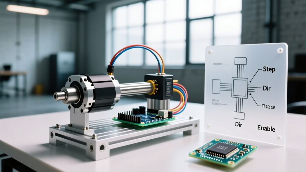
Mastering stepper motor control with Arduino extends far beyond the breadboard. The electrical signals must translate flawlessly into mechanical work. When mounting your NEMA 17 to your linear rail, use a flexible spider coupling (typically 5mm to 8mm) between the motor shaft and the lead screw. This coupling absorbs minor angular misalignments that would otherwise bind the lead screw nut and cause the exact missed steps we aim to avoid.
By combining the high-torque 17HS4401 motor, the silent and intelligent TMC2209 driver, a robust 24V power architecture, and trapezoidal motion profiling via AccelStepper, you elevate your project from a fragile hobbyist prototype to a reliable, industrial-grade automation system capable of running 24/7 in real-world environments.