
The Hidden Cost of Uncalibrated Sensor Displays
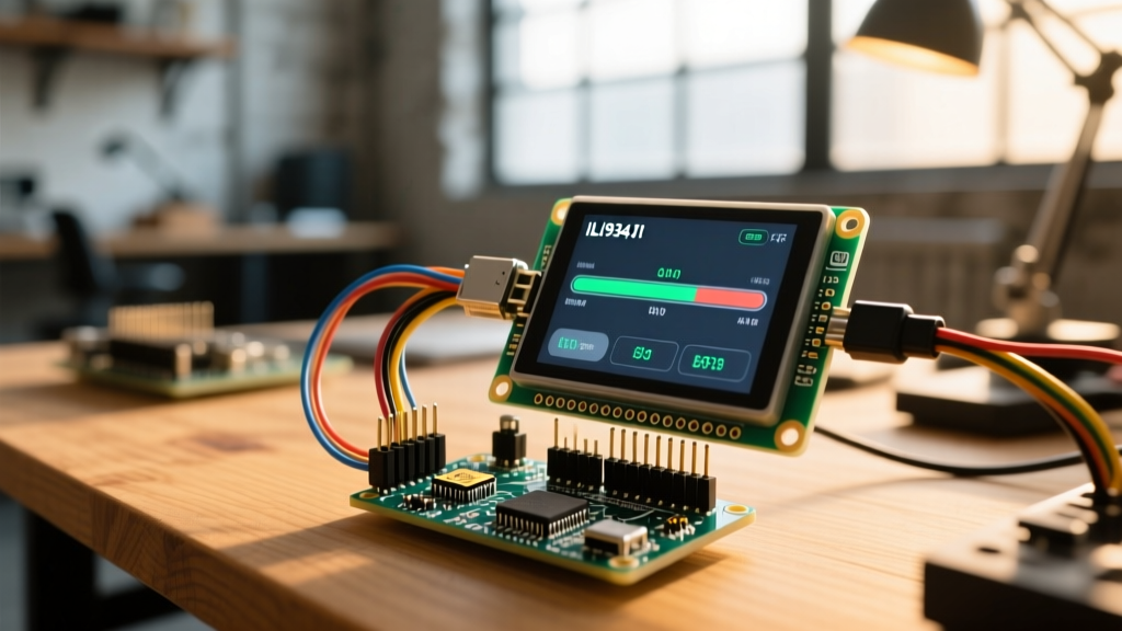
Wiring a TFT or OLED screen to a microcontroller is only the first step in building a reliable instrumentation panel. When you integrate a display Arduino setup for sensor readouts—such as a DIY reflow oven controller, a multi-channel weather station, or a benchtop power supply monitor—uncalibrated touch inputs and washed-out color mappings can render your device unusable. In 2026, while high-end consumer electronics rely on pre-calibrated capacitive matrices, the DIY and prototyping space still heavily utilizes 4-wire resistive touchscreens (like the XPT2046 controller) and raw ILI9341 TFT panels due to their low cost ($12–$18 for 3.5-inch variants) and glove-compatible operation.
However, resistive screens suffer from mechanical tolerance drift, and SPI-driven displays often exhibit color banding if timing and voltage references are not meticulously calibrated. This guide provides a deep-dive engineering approach to calibrating touch alignment, SPI timing, and color accuracy for Arduino-driven displays.
Resistive Touch Drift: The Physics and the Fix
Unlike capacitive screens that detect the electrical properties of the human body, 4-wire resistive touchscreens operate by measuring voltage gradients across two flexible, ITO-coated layers. When pressed, the layers make contact, and the microcontroller's ADC (Analog-to-Digital Converter) reads the voltage drop to determine the X and Y coordinates.
The primary failure mode in these display Arduino integrations is touch drift. This occurs due to:
- Temperature Fluctuations: The resistance of the ITO coating changes with ambient temperature, altering the voltage gradient.
- Mechanical Stress: Repeated pressing on the edges of the bezel causes micro-tears or delamination in the flexible membrane, skewing the ADC readings at the periphery.
- Reference Voltage Sag: If the Arduino's 5V rail sags under load (e.g., when a relay module switches on), the ADC reference voltage drops, causing the touch coordinates to shift dynamically.
Step-by-Step XPT2046 Calibration Matrix
To map raw ADC values to screen pixels, you must establish a boundary matrix. Using the XPT2046_Touchscreen library, we sample the raw 12-bit ADC values at the four corners of the display. For a standard 320x240 ILI9341 display, the raw values rarely map perfectly to 0-320 and 0-240.
| Screen Corner | Raw X (ADC) | Raw Y (ADC) | Mapped Pixel X | Mapped Pixel Y |
|---|---|---|---|---|
| Top-Left | 380 | 340 | 0 | 0 |
| Top-Right | 3750 | 320 | 320 | 0 |
| Bottom-Left | 390 | 3800 | 0 | 240 |
| Bottom-Right | 3780 | 3820 | 320 | 240 |
Once these boundary values are captured, you use the Arduino map() function to translate real-time touches. According to the official Arduino map() reference, the function linearly interpolates the value. However, to prevent out-of-bounds errors when the user presses the plastic bezel, you must wrap the mapping in a constrain() function:
int pixelX = constrain(map(rawX, 380, 3780, 0, 320), 0, 320);
int pixelY = constrain(map(rawY, 320, 3820, 0, 240), 0, 240);
ILI9341 Color Accuracy and SPI Timing Calibration
A common complaint in display Arduino projects is "color banding" or "pixel tearing" when rendering sensor graphs (e.g., drawing a real-time sine wave from an oscilloscope module). This is rarely a defect in the screen itself; it is an SPI bus timing and capacitance issue.
Tuning the SPI Clock Speed
The ILI9341 controller supports SPI clock speeds up to 10MHz for read operations and 62.5MHz for write operations. However, when using jumper wires or a standard solderless breadboard, the parasitic capacitance of the traces degrades the signal integrity at high frequencies. If you push the SPI clock to 40MHz on a breadboard, the display will exhibit ghosting, inverted colors, or diagonal tearing.
Actionable Calibration Rule:
- Breadboard / Long Wires (>10cm): Initialize the display at
16000000(16 MHz). - Custom PCB / Short Traces (<5cm): Safely push to
40000000(40 MHz) for buttery-smooth graph rendering.
Gamma Correction for Sensor Readouts
Out of the box, ILI9341 panels use a default gamma curve optimized for photographs, which makes dark-colored sensor data (like deep blue lines on a black background) nearly invisible. You can calibrate the gamma registers via the Adafruit_ILI9341 library by sending custom initialization commands. Adjusting the ILI9341_GAMMASET register to a linear curve ensures that a 50% PWM backlight or a mid-range sensor value translates to a perceptually accurate 50% luminance on the screen.
Logic Level Shifting: The Hidden Calibration Killer
Perhaps the most catastrophic mistake in display Arduino wiring is connecting a 5V Arduino Uno directly to a 3.3V TFT display without level shifting. While the display might "work" initially, the 5V logic high on the SPI and Touch Chip Select (CS) pins slowly degrades the input protection diodes on the ILI9341 and XPT2046 chips.
More importantly for calibration, feeding 5V into a 3.3V touch controller causes the internal voltage reference to fluctuate, resulting in erratic, non-linear ADC touch mappings. To maintain strict accuracy, you must use a bidirectional logic level shifter (like the BSS138 MOSFET-based modules or a CD4050B buffer). As detailed in SparkFun's guide on logic level shifting, properly translating the 5V signals down to 3.3V stabilizes the touch ADC reference, eliminating the "jitter" often seen in raw touch coordinates.
Expert Insight: If you are using an ESP32 instead of an Arduino Uno, you bypass the logic shifting requirement entirely, as the ESP32 operates natively at 3.3V. However, the ESP32's ADC is notoriously non-linear at the extremes (near 0V and 3.3V). When wiring a resistive touch screen to an ESP32, always use a dedicated external ADC like the ADS1115 via I2C for touch reading, rather than the ESP32's internal ADC pins.
Comprehensive Troubleshooting Matrix
When your sensor data visualization fails or the UI becomes unresponsive, use this diagnostic matrix to isolate the hardware or software fault.
| Symptom | Root Cause | Calibration / Hardware Fix |
|---|---|---|
| Touch registers 20px away from physical stylus | Uncalibrated boundary matrix or swapped X/Y axes | Run raw ADC diagnostic sketch; update TS_MINX and TS_MAXY constants. |
| Screen displays white noise or inverted colors | SPI clock too high for wire capacitance | Drop tft.begin() SPI parameter from 40MHz to 16MHz. |
| Touch works, but screen remains black | Backlight (LED) pin floating or insufficient current | Tie LED pin to 3.3V via a 22Ω resistor; do not drive directly from a GPIO. |
| Random "ghost touches" at screen edges | Electromagnetic interference (EMI) from nearby relays | Add a 100nF decoupling capacitor across the touch controller VCC and GND. |
| Color banding on gradient sensor graphs | Incorrect RGB565 color space conversion | Ensure sensor floats are mapped to 16-bit integers using proper bit-shifting. |
Final Thoughts on Peripheral Integration
Achieving true accuracy in a display Arduino project requires moving beyond simple copy-paste wiring diagrams. By establishing a rigorous touch boundary matrix, respecting SPI capacitance limits, and stabilizing your voltage references with proper logic level shifting, you transform a jittery, unreliable prototype into a precision instrument. Whether you are building a 2026 smart-home environmental monitor or a custom automotive diagnostic tool, these calibration protocols ensure your peripheral interfaces are as accurate as the sensors driving them.
For further reading on optimizing TFT graphics rendering and memory buffering, consult the Adafruit TFT Touch Shield documentation, which provides excellent baseline diagnostic sketches for verifying your specific hardware revision.