
The Evolution of Arduino Stepper Driver Shields
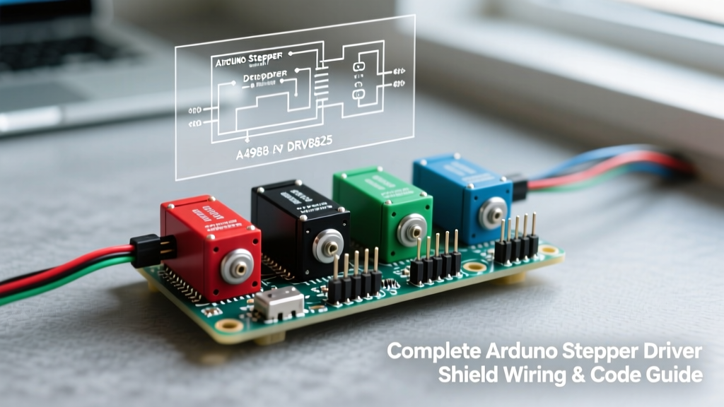
Building high-precision desktop CNCs, camera sliders, or multi-axis robotic arms requires precise motor control that a standard microcontroller cannot provide natively. An Arduino stepper driver shield bridges this gap, translating low-voltage logic signals into high-current phase switching for bipolar stepper motors. In 2026, the DIY automation space has largely standardized around two distinct architectures: the high-voltage, microstepping-focused CNC Shield V3 (paired with DRV8825 or A4988 drivers), and the I2C-based Adafruit Motor Shield V2. While both are excellent, they serve fundamentally different use cases.
This comprehensive wiring and code guide focuses primarily on the CNC Shield V3 with DRV8825 drivers, as it remains the undisputed champion for high-torque, high-resolution multi-axis projects. We will cover exact pinouts, critical Vref tuning procedures, and advanced multi-axis code implementation using the AccelStepper library.
Hardware Selection Matrix: CNC Shield V3 vs. Adafruit V2
Before cutting wires, it is vital to select the correct shield for your project's torque and resolution requirements. Below is a 2026 hardware comparison to help you decide.
| Feature | Protoneer CNC Shield V3 + DRV8825 | Adafruit Motor Shield V2 |
|---|---|---|
| Driver IC | DRV8825 (Replaceable) | TB6612FNG (SMD, fixed) |
| Max Voltage | 8.2V to 45V (Optimal at 24V) | 5V to 12V |
| Max Current per Phase | 2.5A (with active cooling) | 1.2A (continuous) |
| Microstepping | Up to 1/32 step | Up to 1/16 step |
| Communication | Direct GPIO (Hardware Interrupts) | I2C (via PWM/Servo chip) |
| Avg 2026 Price | $12 - $18 (Shield + 3 Drivers) | $24 - $29 (Shield only) |
Expert Insight: If your project requires moving heavy gantries (like a Shapeoko-style CNC or a heavy-duty filament extruder), the CNC Shield V3 running at 24V is mandatory. The Adafruit V2 is better suited for low-torque pan/tilt camera heads or small 3D printer extruders where I2C pin-saving is prioritized over raw torque.
Step-by-Step Wiring Guide for the CNC Shield V3
Wiring an Arduino stepper driver shield incorrectly is the fastest way to permanently destroy your microcontroller or driver ICs. Follow this exact sequence to ensure hardware safety.
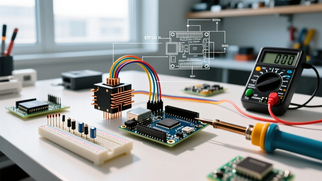
1. Identifying Stepper Motor Coil Pairs (The Multimeter Trick)
Bipolar stepper motors typically have four wires (e.g., NEMA 17 or NEMA 23). You must pair them correctly into Coil A and Coil B. Do not rely on wire color codes, as manufacturers frequently change them.
- Set your digital multimeter to continuity or resistance (Ohms) mode.
- Test pins 1 and 2. If you read a low resistance (typically 1.5Ω to 10Ω), they are a pair. Label them A1 and A2.
- Test pins 3 and 4. They will show a similar low resistance. Label them B1 and B2.
- If you test across coils (e.g., 1 and 3), the multimeter should read infinite resistance (OL).
Insert Coil A into the 1A and 1B slots on the shield, and Coil B into the 2A and 2B slots. Reversing A and B will simply reverse the motor's logical direction, which can be fixed in software.
2. Configuring Microstepping Jumpers
Microstepping divides a full step (usually 1.8° or 200 steps/rev) into smaller fractions, resulting in smoother motion and reduced resonance. The CNC Shield V3 uses three jumpers (M0, M1, M2) located directly beneath the DRV8825 socket. According to the Texas Instruments DRV8825 datasheet, the jumper configuration for 1/16th and 1/32nd microstepping is as follows:
- Full Step: M0 (Out), M1 (Out), M2 (Out)
- 1/8 Step: M0 (In), M1 (In), M2 (Out)
- 1/16 Step: M0 (Out), M1 (Out), M2 (In)
- 1/32 Step: M0 (In), M1 (In), M2 (In)
Note: "In" means the jumper cap is placed over the two header pins; "Out" means the pins are left bare.
3. Power Supply Selection and Vref Tuning (Critical Step)
The most common failure mode for beginners is skipping the Vref (Reference Voltage) tuning, leading to overheated drivers and melted stepper coils. The DRV8825 current limit is dictated by the onboard potentiometer.
The Formula: Current Limit = Vref × 2
If you are using a standard NEMA 17 motor rated for 1.5A per phase, your target Vref is 0.75V.
- Power the Arduino via USB and connect your main 24V DC power supply to the CNC Shield's barrel jack or terminal block.
- Set your multimeter to DC Voltage (20V range).
- Place the black probe on the shield's ground pin and the red probe on the metal shaft of the DRV8825 trim potentiometer.
- Use a ceramic screwdriver (never metal, to avoid shorting) to turn the pot clockwise to increase voltage, or counter-clockwise to decrease it.
- Lock it in at exactly 0.75V for a 1.5A motor.
Writing the Code: Multi-Axis Control with AccelStepper
The default Arduino Stepper.h library is blocking, meaning it halts the microcontroller while a motor moves. For an Arduino stepper driver shield controlling multiple axes simultaneously, you must use the AccelStepper library by Mike McCauley. It utilizes non-blocking algorithms, allowing the X and Y axes to accelerate, move, and decelerate concurrently.
Below is the foundational code for independent X and Y axis control using the standard Protoneer CNC Shield V3 pin mappings.
#include <AccelStepper.h>

// CNC Shield V3 Pin Definitions
#define X_STEP_PIN 2
#define X_DIR_PIN  5
#define Y_STEP_PIN 3
#define Y_DIR_PIN  6
#define ENABLE_PIN 8

// Initialize AccelStepper objects (DRIVER mode = 1)
AccelStepper stepperX(AccelStepper::DRIVER, X_STEP_PIN, X_DIR_PIN);
AccelStepper stepperY(AccelStepper::DRIVER, Y_STEP_PIN, Y_DIR_PIN);

void setup() {
  // Enable the DRV8825 drivers (Active LOW on CNC Shield)
  pinMode(ENABLE_PIN, OUTPUT);
  digitalWrite(ENABLE_PIN, LOW);

  // Configure X-Axis Parameters
  stepperX.setMaxSpeed(3200);      // Steps per second (1/16 microstepping)
  stepperX.setAcceleration(1600);  // Steps per second squared
  stepperX.moveTo(6400);           // Move 2 full revolutions (200 * 16 * 2)

  // Configure Y-Axis Parameters
  stepperY.setMaxSpeed(1600);
  stepperY.setAcceleration(800);
  stepperY.moveTo(-3200);          // Move 1 full revolution in reverse
}

void loop() {
  // Non-blocking movement execution
  if (stepperX.distanceToGo() != 0) {
    stepperX.run();
  }
  if (stepperY.distanceToGo() != 0) {
    stepperY.run();
  }

  // Add logic here to trigger new moves once distanceToGo() == 0
}
As detailed in the Protoneer CNC Shield documentation, the Enable pin (D8) is active LOW. Forgetting to pull D8 LOW in your setup() function will result in the drivers remaining disabled, leaving the motors completely unpowered and unresponsive.
Advanced Troubleshooting & Edge Cases
Even with perfect wiring, high-speed stepper applications introduce electrical noise and mechanical resonance. Here is how to solve the most common edge cases encountered in 2026 DIY builds.
Ghost Stepping and EMI Interference
Symptom: The motor randomly steps or vibrates when idle, or the Arduino resets unexpectedly during high-speed traversal.
Cause: Electromagnetic Interference (EMI) from unshielded stepper cables acting as antennas, injecting noise into the Arduino's 5V logic lines.
Solution:
- Keep stepper motor cables under 1.5 meters. Longer runs require shielded cables with the shield grounded at the controller end only.
- Twist the stepper motor wires (A1 with A2, B1 with B2) tightly to cancel out magnetic fields.
- Solder a 100nF ceramic capacitor directly between the STEP and DIR pins and Ground on the CNC shield to filter high-frequency logic noise.
Thermal Throttling and Mid-Cycle Stalling
Symptom: The motor runs perfectly for 3 minutes, then suddenly stalls or loses steps, resuming only after it cools down.
Cause: The DRV8825's internal thermal shutdown protection is triggering at 150°C. This happens when the Vref is set too high, or the driver lacks adequate convective cooling.
Solution: Re-verify your Vref. If the current limit is correct, you must upgrade the heatsink. The standard peel-and-stick aluminum heatsinks provided in cheap 2026 Amazon kits are insufficient for currents above 1.2A. Upgrade to a 40mm active cooling fan blowing directly across the shield, or switch to external DM542T industrial drivers if your application demands continuous 3A+ operation.
Summary
Mastering an Arduino stepper driver shield requires moving beyond basic plug-and-play assumptions. By rigorously identifying coil pairs, mathematically tuning the Vref potentiometer, and leveraging the non-blocking capabilities of the AccelStepper library, you transform a basic microcontroller into a highly reliable industrial motion controller. Whether you are building a pen plotter or a 4-axis robotic arm, these foundational wiring and coding practices will ensure your hardware survives and your motion profiles remain flawlessly smooth.