
The Core Challenge of Field Sensor Telemetry
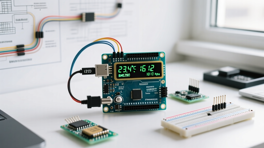
When prototyping environmental monitors, relying solely on the Arduino IDE Serial Monitor is insufficient for deployed, standalone units. Learning how to use an LCD screen with Arduino to display real-time sensor telemetry bridges the gap between a breadboard prototype and a functional field instrument. In this integration tutorial, we will interface a standard 16x2 I2C LCD with a Bosch BME280 environmental sensor to create a standalone temperature, humidity, and barometric pressure readout.
Unlike parallel LCDs that consume six or more digital I/O pins, an I2C (Inter-Integrated Circuit) backpack reduces the wiring footprint to just two data lines (SDA and SCL), freeing up microcontroller pins for additional peripherals.
Bill of Materials (BOM) & Component Selection
Component selection directly impacts bus stability and readability. As of 2026, while the classic Arduino Uno R3 remains a staple, many engineers are migrating to the Arduino Uno R4 Minima ($20.00) for its 32-bit ARM Cortex-M4 processor, though the I2C implementation for this tutorial remains identical across both architectures.
- Microcontroller: Arduino Uno R3 ($27.60) or Uno R4 Minima ($20.00).
- Display: 1602A LCD Module with PCF8574T I2C Backpack (Generic, ~$3.50). Ensure the backpack is soldered securely; cold joints on the 16-pin header are a leading cause of ghosting.
- Sensor: Bosch BME280 Breakout Board. We recommend the Adafruit BME280 (Product ID: 2652) ($14.95) for its onboard 3.3V LDO and logic level shifting, or a generic 5-pin module (~$4.50) if you are strictly operating at 3.3V.
- Passives: 2.2kΩ and 4.7kΩ pull-up resistors (for bus capacitance tuning).
I2C Bus Wiring Topology
Both the PCF8574T LCD backpack and the BME280 sensor communicate via the I2C protocol. Because they operate on the same bus, they must have unique hardware addresses. The Arduino Uno's hardware I2C pins are A4 (SDA) and A5 (SCL).
| Component Pin | Arduino Uno Pin | Notes & Caveats |
|---|---|---|
| LCD VCC | 5V | PCF8574T requires 5V for proper logic high thresholds and backlight illumination. |
| LCD GND | GND | Common ground is mandatory for I2C reference voltage. |
| LCD SDA | A4 (SDA) | Connect in parallel with the sensor SDA line. |
| LCD SCL | A5 (SCL) | Connect in parallel with the sensor SCL line. |
| BME280 VIN | 5V | Only if using a breakout with an onboard LDO (like Adafruit). Raw modules need 3.3V. |
| BME280 GND | GND | Common ground. |
| BME280 SDA | A4 (SDA) | Shared I2C data line. |
| BME280 SCL | A5 (SCL) | Shared I2C clock line. |
Resolving the I2C Address Conflict
Before uploading the integration sketch, you must verify the I2C addresses of your peripherals. The Arduino Wire library requires exact hexadecimal addresses to initialize communication.
Expert Insight: Most generic 1602 LCDs with a PCF8574T chip default to
0x27. However, if your backpack uses the PCF8574AT chip variant, the address will be0x3F. Always run an I2C Scanner sketch first to prevent silent initialization failures.
The BME280 default address is 0x77 (if the SDO pin is left floating or pulled to GND) or 0x76 (if SDO is pulled to VCC). Adafruit breakouts default to 0x77.
The Integration Sketch
This sketch utilizes the LiquidCrystal_I2C library by Frank de Brabander and the Adafruit_BME280 library. Ensure both are installed via the Arduino Library Manager.
#include <Wire.h>
#include <LiquidCrystal_I2C.h>
#include <Adafruit_Sensor.h>
#include <Adafruit_BME280.h>

// Initialize LCD at address 0x27, 16 columns, 2 rows
LiquidCrystal_I2C lcd(0x27, 16, 2);

Adafruit_BME280 bme;

void setup() {
  Serial.begin(115200);

  // Initialize LCD
  lcd.init();
  lcd.backlight();
  lcd.setCursor(0, 0);
  lcd.print("Initializing...");

  // Initialize BME280
  if (!bme.begin(0x77)) {
    lcd.clear();
    lcd.print("BME280 Error!");
    Serial.println("Could not find BME280 sensor. Check wiring.");
    while (1) { delay(10); }
  }

  lcd.clear();
}

void loop() {
  float tempC = bme.readTemperature();
  float humidity = bme.readHumidity();
  float pressurePa = bme.readPressure();

  // Format and display Temperature & Humidity on Row 1
  lcd.setCursor(0, 0);
  lcd.print("T:");
  lcd.print(tempC, 1);
  lcd.print("C H:");
  lcd.print(humidity, 0);
  lcd.print("% ");

  // Format and display Pressure on Row 2
  lcd.setCursor(0, 1);
  lcd.print("P:");
  lcd.print(pressurePa / 100.0F, 1);
  lcd.print(" hPa   ");

  delay(2000); // 2-second telemetry refresh rate
}
Advanced Troubleshooting: Ghosting & Bus Capacitance
When learning how to use an LCD screen with Arduino alongside multiple sensors, you may encounter 'ghosting' (faint, incorrect characters appearing on the display) or complete bus lockups. This is rarely a software issue; it is almost always a violation of I2C physical layer specifications.
1. The 400pF Capacitance Limit
According to the NXP I2C Bus Specification (UM10204), the total bus capacitance must not exceed 400pF. Long jumper wires, breadboard stray capacitance, and the input capacitance of the LCD backpack and sensor can easily push the bus beyond this limit, degrading the square wave clock signal into a slow, unreadable ramp.
Solution: If your total wire length exceeds 30cm, reduce the I2C pull-up resistors from the standard 4.7kΩ to 2.2kΩ. This provides a stronger current source to charge the bus capacitance faster, restoring sharp signal edges.
2. The Contrast Trimpot Oversight
A completely blank LCD with the backlight on is the most common beginner failure mode. The PCF8574T backpack features a blue trimpot on the rear. Using a small Phillips screwdriver, turn this potentiometer clockwise or counter-clockwise while the Arduino is powered. You are adjusting the voltage differential across the liquid crystal fluid. Stop when the character block outlines are faintly visible behind the active text.
3. Backlight Current Limiting
The jumper located on the I2C backpack bridges the VCC to the LED backlight anode. While most modern 1602 modules include an onboard 10Ω or 47Ω current-limiting resistor, some ultra-cheap clones omit it. If your backlight is blindingly bright or the PCF8574T chip becomes hot to the touch, remove the jumper and wire the backlight through a 100Ω resistor to a 5V digital pin, allowing you to toggle the backlight via software to save power in battery-operated deployments.
Frequently Asked Questions
Can I use a 20x4 LCD instead of a 16x2?
Yes. The PCF8574T I2C backpack is pin-compatible with 2004A LCD modules. You only need to change the initialization line in your code to LiquidCrystal_I2C lcd(0x27, 20, 4); and adjust your lcd.setCursor() coordinates to utilize the 4 available rows.
Why does my LCD display black boxes on the first row?
Black boxes indicate that the LCD controller (usually the Hitachi HD44780) is receiving power and initializing its internal RAM, but it is not receiving data from the Arduino. This is caused by an incorrect I2C address in the code, or a disconnected SDA/SCL line. Run an I2C scanner sketch to verify the exact hexadecimal address of your specific backpack.