
The Reality of LCD Integration
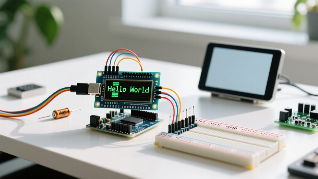
There are few things more frustrating in embedded prototyping than wiring up a classic 16x2 character display, uploading your sketch, and being greeted by a blank, glowing white screen. While learning how to connect LCD to Arduino hardware is a rite of passage, the reality of breadboard parasitic resistance, I2C address conflicts, and library mismatches often derails both beginners and veterans. In 2026, despite the rise of OLEDs and TFTs, the Hitachi HD44780-compatible 16x2 LCD remains a staple in industrial control panels and DIY test equipment due to its ruggedness and low cost (typically $4.50 for parallel, $5.80 with an I2C backpack).
This troubleshooting guide bypasses basic tutorials and dives straight into the edge cases, failure modes, and electrical realities of LCD integration.
Hardware Matrix: Parallel vs. I2C Backpack
Before troubleshooting, you must identify your interface. The raw 16-pin parallel interface consumes six digital I/O pins, while the PCF8574 I2C expander backpack reduces this to just two (SDA/SCL). Here is how they compare in real-world bench conditions:
| Feature | 16-Pin Parallel (Raw HD44780) | I2C Backpack (PCF8574/PCF8574A) |
|---|---|---|
| Wiring Complexity | High (12 active connections) | Low (4 connections: VCC, GND, SDA, SCL) |
| MCU Pin Consumption | 6 Digital Pins (4-bit mode) | 2 Pins (Hardware or Software I2C) |
| Avg. Cost (2026) | $3.50 - $4.50 | $5.50 - $6.50 (LCD + Soldered Backpack) |
| Primary Failure Point | Floating RW pin, loose breadboard wires | Incorrect I2C address, SDA/SCL swap |
| Recommended Library | LiquidCrystal (Built-in) | hd44780 by Bill Perry |
Troubleshooting the 'Blank White Screen'
If your backlight is on but the screen is completely blank (no dark blocks, no text), you are almost certainly dealing with a contrast or logic initialization failure.
1. The Contrast Voltage Divider (V0 Pin)
Pin 3 (V0) controls the liquid crystal bias voltage. It does not accept a simple HIGH/LOW digital signal; it requires an analog voltage between 0.2V and 1.0V relative to ground to render characters. If V0 is tied directly to 5V, the screen will be blank. If tied directly to GND, you will see 16 solid white blocks.
- Parallel Fix: Ensure you have a 10kΩ potentiometer wired as a voltage divider. Wiper to V0, outer legs to 5V and GND. Measure the wiper voltage with a multimeter; aim for 0.6V.
- I2C Backpack Fix: Locate the tiny blue trimpot on the PCF8574 backpack. Use a precision jeweler's screwdriver to turn it counterclockwise while the Arduino is powered. You will see dark blocks appear, then text.
2. The RW Pin Trap (Parallel Only)
Pin 5 (RW) dictates Read/Write mode. Most basic Arduino tutorials operate the LCD in write-only mode. If you leave the RW pin floating, it acts as an antenna, picking up electromagnetic noise and randomly toggling the LCD into 'Read' mode. When in Read mode, the HD44780 controller ignores incoming data, resulting in a blank screen.
Always hardwire the RW pin (Pin 5) directly to GND when using the standard 4-bit parallel LiquidCrystal library. Never leave it floating.
Parallel Wiring: The 4-Bit Mode Pitfalls
When bypassing I2C and wiring directly in 4-bit mode, you only use data pins D4 through D7. A frequent mistake is wiring D0-D3 by habit, then initializing the Arduino library in 4-bit mode. The HD44780 initializes in 8-bit mode by default on power-up. The library sends a specific sequence of three 8-bit commands (using only the upper nibble) to force the controller into 4-bit mode. If your physical wiring connects to D0-D3 instead of D4-D7, this initialization handshake fails silently, leaving the display in an unresponsive 8-bit state.
- RS (Register Select): Must be connected to a digital pin. LOW = Command, HIGH = Data.
- EN (Enable): The clock pin. Must pulse HIGH then LOW to latch data. Ensure your breadboard contacts are clean; a weak EN pulse will result in missed characters.
- D4-D7: The upper nibble. Double-check your pinout against the specific LCD manufacturer's datasheet, as some rare 16-pin layouts invert the pin order (Pin 1 on the right instead of the left).
I2C Nightmares: Address Scanning and SDA/SCL Swaps
When using an I2C backpack, the most common reason for a blank screen is an address mismatch in your code. Manufacturers use two different I/O expanders: the PCF8574 and the PCF8574A. According to the NXP PCF8574 datasheet, the base I2C addresses differ based on the silicon revision and the state of the A0, A1, and A2 jumper pads on the backpack.
Step-by-Step I2C Address Recovery
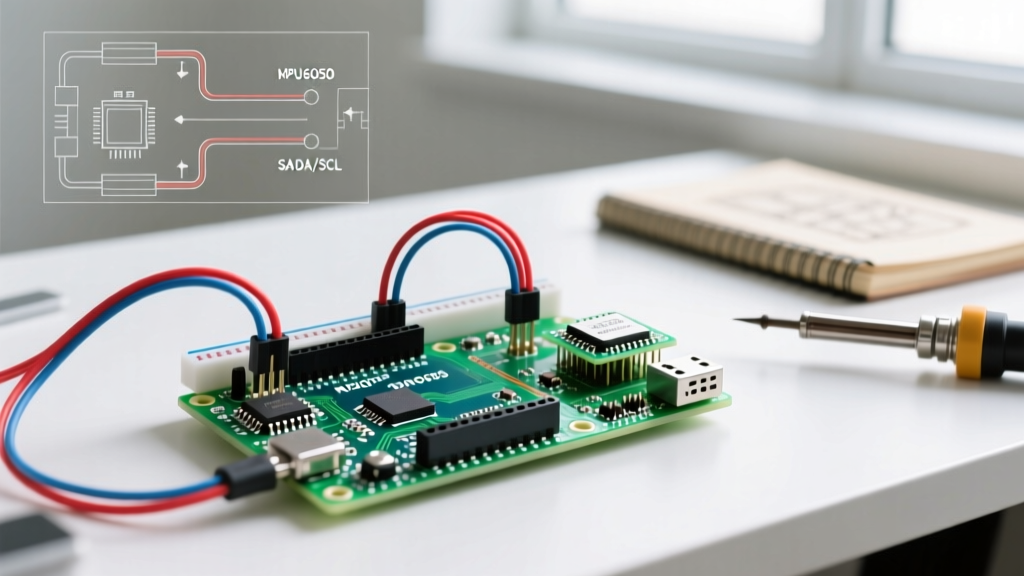
- Verify Wiring: On an Arduino Uno R3, SDA is A4 and SCL is A5. On the newer Arduino Uno R4 Minima/WiFi, SDA and SCL are strictly on the dedicated header pins near the AREF pin. Swapping these will silently fail without throwing a compilation error.
- Run an I2C Scanner: Flash Nick Gammon's I2C Scanner sketch or use the built-in Arduino IDE example (File > Examples > Wire > I2CScanner).
- Interpret the Hex Output: If the Serial Monitor outputs
0x27, you likely have a PCF8574A chip. If it outputs0x3F, it is usually a standard PCF8574. Update your code's constructor accordingly:LiquidCrystal_I2C lcd(0x27, 16, 2); - Check the Backlight Jumper: Most I2C backpacks feature a 2-pin jumper near the VCC pin. If this jumper is removed, the backlight circuit is broken, making the screen appear blank in ambient light even if characters are rendering.
Software Conflicts: Upgrading Your Library Stack
In 2026, the legacy LiquidCrystal_I2C library by Frank de Brabander is largely considered outdated. It hardcodes pin mappings that fail on 40% of cheap clone backpacks imported from overseas, because manufacturers arbitrarily route the PCF8574 expander pins to the LCD's RS, RW, EN, and D4-D7 pins.
The definitive solution is the hd44780 library by Bill Perry. This library is a masterpiece of embedded engineering. It utilizes an auto-detection diagnostic sketch that probes the I2C bus, identifies the exact address, and dynamically maps the internal pin routing of the backpack without requiring manual hex-bitmask calculations.
Implementation Guide
- Install
hd44780via the Arduino Library Manager. - Include
<Wire.h>and<hd44780_I2Cexp.h>. - Instantiate the display simply with
hd44780_I2Cexp lcd;— no address or pin mapping required in the constructor. - Run the I2CexpDiag example sketch first. This will test the I2C bus integrity, verify RAM, and confirm the exact pin mapping on your Serial Monitor.
Edge Cases: Power Sag and 3.3V Logic Mismatches
If your LCD initializes perfectly on boot but turns blank or displays garbage characters when a motor or relay activates, you are experiencing VCC rail sag.
The AMS1117 Thermal Bottleneck
Standard Arduino Uno clones utilize the AMS1117-5.0 linear voltage regulator. A 16x2 LCD with an active LED backlight draws between 80mA and 120mA. If you are powering the Arduino via the barrel jack at 9V, the regulator must dissipate 4V across it at 120mA, generating roughly 0.48W of heat. Without adequate heatsinking, the regulator's thermal shutdown kicks in, dropping the 5V rail to 4.1V. The HD44780 controller requires a minimum of 4.5V for stable logic operations; below this, the internal CGRAM corrupts, resulting in Japanese characters or a blank screen.
The Fix: Power the LCD backlight directly from the Arduino's 5V USB pin (which bypasses the linear regulator when connected to a PC), or use a dedicated 5V buck converter module (like the LM2596) for projects involving relays and displays.
ESP32 and 3.3V Logic Warnings
Standard HD44780 LCDs are 5V TTL devices. While they will often 'work' when connected to the 3.3V logic pins of an ESP32 or Arduino Due, the HIGH threshold (VIH) for the HD44780 is technically 2.2V minimum, but noise margins are severely compressed. More importantly, the backlight requires 5V and up to 120mA, which will instantly fry the 3.3V voltage regulator on an ESP32 DevKit V1 if you attempt to draw backlight current from the board's 3V3 pin. Always use a logic level shifter (like the BSS138 bidirectional MOSFET module) and an independent 5V power rail for the display when working with 3.3V microcontrollers.
Quick Diagnostic Checklist
Keep this checklist at your bench when a display refuses to cooperate:
- Multimeter Check: Measure VCC at the LCD pins (not the Arduino header). Is it ≥ 4.7V?
- Contrast Check: Is V0 between 0.2V and 1.0V?
- Scanner Check: Does the I2C scanner reliably find the address without intermittent drops?
- Library Check: Have you migrated to the auto-detecting
hd44780library? - Grounding Check: Are the Arduino GND and the LCD GND tied together on the same bus bar?