
Introduction: Beyond the Blue Module
When building home automation or industrial control prototypes, the intersection of arduino and relay circuits is unavoidable. Most makers purchase the ubiquitous blue 5V relay module, wire it to a digital pin, and toggle it with digitalWrite(). However, when the ATmega328P microcontroller randomly resets, or the relay contacts weld shut while switching a water pump, the answers lie buried in the component datasheet. In 2026, while solid-state relays (SSRs) have become more affordable, mechanical electromagnetic relays remain the standard for high-surge, cost-sensitive prototyping.
This datasheet explainer dissects the most common relay found on these modules—the Songle SRD-05VDC-SL-C (and its premium equivalents like the Omron G5LE)—to bridge the gap between raw datasheet specifications and real-world Arduino integration.
The Coil Circuit: Why Your Arduino GPIO Cannot Drive It Directly
The first section of any relay datasheet details the coil characteristics. The coil is an electromagnet that physically pulls the metal contact. According to the Songle SRD-05VDC datasheet, the nominal coil voltage is 5VDC, and the coil resistance is approximately 70Ω.
Calculating the Current Draw
Using Ohm's Law (I = V/R), we can determine the current required to energize the coil:
- Voltage: 5V
- Resistance: 70Ω
- Current: 5V / 70Ω = ~71.4mA
Critical Datasheet Warning: The absolute maximum DC current per I/O pin on the Arduino Uno's ATmega328P is 40mA, with a recommended operating limit of 20mA. Attempting to drive a 71mA relay coil directly from a GPIO pin will cause catastrophic thermal failure of the microcontroller's internal silicon. Always use the transistor driver circuit included on standard relay modules.
Standard modules use an NPN transistor (typically an S8050 or 2N2222) to amplify the GPIO's meager 5mA-20mA signal into the 71mA required by the coil. When reviewing a module's schematic, ensure the base resistor is sized correctly (usually 1kΩ) to saturate the transistor without overloading the Arduino pin.
Decoding Contact Ratings: The '10A Myth' and Inductive Derating
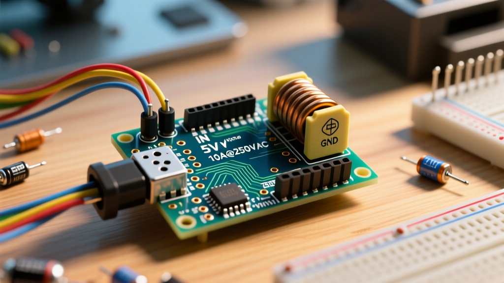
The most misunderstood section of the relay datasheet is the contact rating. The Songle SRD-05VDC is stamped with 10A 250VAC and 10A 30VDC. Beginners often assume this means they can safely switch any 10-amp load. This is a dangerous misconception that leads to arcing and fires.
Resistive vs. Inductive Loads
Datasheet ratings are almost exclusively based on purely resistive loads (like heating elements or incandescent bulbs). When you switch an inductive load (like AC motors, solenoids, or transformers), the inrush current can be 6 to 8 times higher than the steady-state running current. Furthermore, when the contacts open, the collapsing magnetic field of the motor generates a massive voltage spike (back-EMF) that sustains an electrical arc across the physical gap of the relay contacts.
For a comprehensive look at premium contact ratings and derating curves, refer to the Omron G5LE Power Relay Datasheet, which provides explicit derating charts for motor loads.
| Load Type | Example Device | Max Safe Continuous Current | Datasheet Derating Factor |
|---|---|---|---|
| Resistive | Space Heater, Toaster | 10A | 100% (Nominal) |
| Capacitive | LED Drivers, SMPS | 3A - 5A | 30% - 50% |
| Inductive (Motor) | HVAC Fan, Water Pump | 1.5A - 2A | 15% - 20% |
| Lamp Load | Tungsten/Halogen Bulbs | 1A - 2A | 10% - 20% |
Optoisolation Deep Dive: The JD-VCC Jumper Explained
High-quality Arduino and relay modules feature a PC817 optocoupler. This component uses an internal LED and a phototransistor to transmit the switching signal via light, providing galvanic isolation between the low-voltage Arduino and the high-voltage relay coil. However, many modules ship with a jumper cap bridging the VCC and JD-VCC pins, which defeats this isolation.
When the jumper is in place, the relay coil's ground is shared with the Arduino's ground. The back-EMF generated when the coil de-energizes can inject noise directly into the microcontroller's power rail, causing brownouts. To achieve true optical isolation, you must remove the jumper and power the JD-VCC pin with a dedicated, isolated 5V power supply.
Arduino and Relay Wiring Matrix for True Isolation
To implement true optical isolation using a standard 5V relay module, follow this wiring matrix. This setup requires two separate 5V power sources (e.g., the Arduino USB/Barrel jack and a secondary 5V buck converter).
| Relay Module Pin | Connect To | Purpose |
|---|---|---|
| GND | Secondary 5V Supply GND | Completes the coil circuit (Isolated from Arduino) |
| JD-VCC | Secondary 5V Supply +5V | Powers the relay coil and optocoupler output |
| VCC | Arduino 5V Pin | Powers the optocoupler input LED |
| IN1 | Arduino GPIO (e.g., Pin 8) | Logic signal to trigger the optocoupler |
Note: Ensure the jumper between VCC and JD-VCC is physically removed before applying power.
Real-World Failure Modes and Datasheet Edge Cases
Even with perfect wiring, mechanical relays degrade over time. Understanding the failure modes documented in relay application notes is crucial for designing robust systems.
1. Contact Welding (The 'Stuck ON' Failure)
If you switch a high-inrush capacitive load (like a large server power supply), the initial current surge can momentarily melt the microscopic peaks on the contact surfaces. As they cool, they fuse together. The relay will remain closed even when the coil is de-energized. Solution: Use an NTC thermistor in series with the load to limit inrush current, or upgrade to a relay with a higher AgSnO2 (Silver Tin Oxide) contact rating.
2. Back-EMF and the Flyback Diode
When the S8050 transistor turns off, the collapsing magnetic field in the 70Ω coil generates a reverse voltage spike that can exceed 50V. This spike will instantly destroy the driving transistor if not clamped. Standard modules include a 1N4007 flyback diode wired in reverse bias across the coil. As detailed in the Texas Instruments SLVA478 Application Note on Inductive Flyback, this diode safely recirculates the decaying current. Never remove or bypass this diode on a custom PCB design.
3. Contact Bounce Time
Datasheets list a contact bounce time (typically 5ms to 10ms for the SRD-05VDC). When the armature slams into the contact, it physically bounces like a basketball before settling. If you are using the relay to switch a digital logic signal or a high-speed communication line, this bounce will be read as multiple rapid triggers. Mechanical relays are unsuitable for high-frequency PWM or data switching; use an SSR or MOSFET instead.
Summary: Designing for the Long Term
Integrating an Arduino and relay requires respecting the physical limits of electromechanical components. By reading the coil resistance to calculate current draw, applying strict derating factors for inductive loads, and utilizing true optical isolation via the JD-VCC jumper, you transition from fragile hobbyist prototypes to reliable, production-grade control systems. Always cross-reference your specific load type against the manufacturer's derating curves before finalizing your hardware design.
For further reading on microcontroller pin limitations and safe current sourcing, consult the official Arduino Digital Pins Documentation.