
The Reality of Multi-Peripheral LDR Arduino Circuits
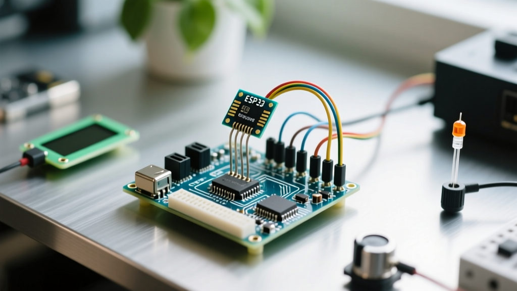
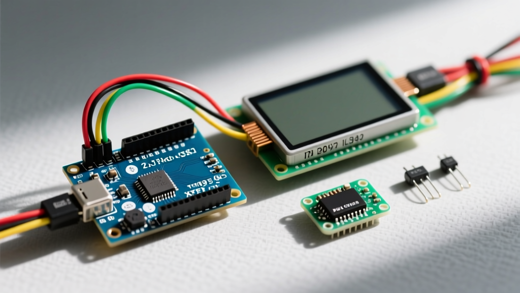
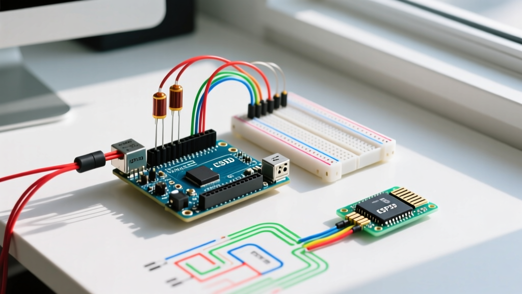
If you have ever built a basic light-sensing circuit, you know that a simple ldr arduino tutorial usually involves a single photoresistor, a 10kΩ resistor, and an LED. However, in 2026, real-world IoT nodes and environmental monitors are rarely that simple. Modern projects require integrating the Light Dependent Resistor (LDR) alongside I2C OLED displays (like the SSD1306), PWM-driven servos, 5V relay modules, and Wi-Fi transceivers.
When you transition from a single-sensor breadboard to a multi-peripheral PCB or complex wiring harness, a common failure mode emerges: ADC noise and erratic analog readings. The moment a relay clicks or an I2C bus transmits data, your LDR's analog values spike or drift. This guide dives deep into the hardware physics and firmware strategies required to stabilize an LDR in a dense, multi-peripheral Arduino environment.
Understanding ADC Crosstalk and Switching Noise
The ATmega328P (and even newer chips like the ATmega4809) uses a single Analog-to-Digital Converter (ADC) with an internal multiplexer. When you read from A0 (your LDR) and then switch to A1 (perhaps a thermistor or current sensor), the internal sample-and-hold (S/H) capacitor must charge to the new voltage level.
If your LDR circuit has a high output impedance, the S/H capacitor cannot charge fully within the ADC's acquisition time (typically 1.5 to 12 ADC clock cycles). This results in 'ghosting' or crosstalk, where the reading on A0 is artificially pulled toward the voltage present on A1. Furthermore, switching peripherals like relays or high-power LEDs introduce high-frequency transient noise onto the 5V VCC rail, which directly modulates your ADC reference voltage, destroying measurement accuracy.
Selecting the Right LDR and Bias Resistor
To minimize output impedance and reduce susceptibility to electromagnetic interference (EMI), your voltage divider must be optimized for the specific LDR model you are using. According to the SparkFun Voltage Divider Tutorial, the bias resistor should ideally match the LDR's resistance at the exact light level (lux) where you need the highest resolution.
| LDR Model | Dark Resistance (kΩ) | Resistance @ 10 Lux (kΩ) | Optimal Bias Resistor | Best Use Case |
|---|---|---|---|---|
| GL5516 | 500 - 1000 | 5 - 10 | 10 kΩ | Indoor ambient light tracking |
| GL5528 | 1000 - 2000 | 10 - 20 | 22 kΩ | Streetlight / Dusk-to-Dawn triggers |
| GL5537-1 | 2000 - 5000 | 20 - 30 | 33 kΩ | Low-light / Night-sky detection |
| VT90N2 | 3000 - 8000 | 12 - 25 | 22 kΩ | High-precision industrial enclosures |
Pro-Tip: Avoid using 100kΩ or 1MΩ bias resistors to 'save power.' While this reduces current draw, it pushes the source impedance well above the 10kΩ maximum recommended by Microchip for the ATmega328P ADC, guaranteeing noisy readings in a multi-peripheral setup.
Hardware Blueprint: Power Delivery and Decoupling
In a multi-peripheral setup, the LDR is at the mercy of your power delivery network (PDN). A standard 5V mechanical relay module draws 70mA to 100mA when the coil energizes. This sudden current demand causes a momentary voltage sag (brownout) on the 5V rail. Since the Arduino's default ADC reference is tied to VCC, a 100mV sag translates directly into a ~20-point drop in your 10-bit ADC reading.
The Decoupling Strategy
To isolate your ldr arduino analog circuit from digital and inductive noise, implement the following decoupling matrix:
- Local LDR Decoupling: Place a 100nF (0.1µF) X7R MLCC ceramic capacitor directly across the VCC and GND pins of the LDR's voltage divider, as close to the A0 pin as physically possible.
- AREF Stabilization: If you are using an external reference (like a 4.096V precision shunt), place a 100nF ceramic cap in parallel with a 10µF tantalum capacitor on the AREF pin to filter high-frequency switching noise from nearby I2C lines.
- Relay Flyback Protection: Never drive a relay coil without a 1N4007 or 1N4148 flyback diode wired in reverse-bias across the coil terminals. Inductive kickback spikes can exceed 50V and will permanently degrade the ADC multiplexer over time.
Warning on ESP32 ADC Non-Linearity: If your multi-peripheral setup uses an ESP32 or ESP32-S3 instead of a classic AVR Arduino, be aware that the internal SAR ADC is notoriously non-linear, especially below 100mV and above 3.1V. For precision light sensing on ESP architectures, bypass the internal ADC entirely and use an external I2C ADC like the Texas Instruments ADS1115 (typically ~$3.50). The Arduino Analog Pins Documentation provides further context on architecture-specific ADC quirks.
Firmware Strategy: Oversampling and Digital Filtering
Hardware fixes only take you so far. In a noisy environment, a single analogRead(A0) call is statistically useless. Relying on the basic Arduino Built-In Smoothing Example (which uses a simple rolling average array) consumes valuable SRAM and introduces latency. Instead, use hardware oversampling combined with an Exponential Moving Average (EMA).
Implementing 12-Bit Resolution via Oversampling
You can artificially increase the resolution of the ATmega328P's 10-bit ADC to 12-bit by oversampling. According to Nyquist and ADC noise theory, adding 1 extra bit of resolution requires 4x oversampling. To get 12 bits (0-4095 range), you must sample 16 times and bit-shift.
Here is the highly optimized C++ implementation for a multi-tasking environment:
uint16_t readOversampledLDR(uint8_t pin) {
  uint32_t sum = 0;
  // Discard first read to clear the ADC multiplexer S/H capacitor
  analogRead(pin);
  delayMicroseconds(50); // Allow S/H cap to settle

  for (uint8_t i = 0; i < 16; i++) {
    sum += analogRead(pin);
  }
  // 16 samples = 4 extra bits. Shift right by 2 to get 12-bit value.
  return (sum >> 2);
}
Exponential Moving Average (EMA) Filter
To smooth out transient spikes caused by I2C OLED refresh cycles without using an array buffer, apply an EMA filter. This requires only a single floating-point or fixed-point integer variable.
float ldrEma = 0;
const float alpha = 0.1; // Lower = smoother but slower response

void updateLightLevel() {
  uint16_t raw = readOversampledLDR(A0);
  ldrEma = (alpha * raw) + ((1.0 - alpha) * ldrEma);
}
Real-World Failure Modes & Troubleshooting
Even with perfect code and decoupling capacitors, multi-peripheral setups can fail in edge cases. Here is a diagnostic checklist for erratic LDR behavior:
- The I2C Bus Capacitance Drag: If you are running an SSD1306 OLED and a BME280 sensor on the same I2C bus as your ADC reads, long wires add parasitic capacitance. This slows down the I2C rise times, causing the microcontroller to spend more time in interrupt service routines (ISRs), which interrupts the ADC sampling timer. Fix: Keep I2C traces under 30cm and use 4.7kΩ pull-ups instead of 10kΩ.
- Ground Loop Interference: If your LDR is mounted remotely (e.g., outside an enclosure) and connected via a 3-wire ribbon cable, the ground wire acts as an antenna for 50/60Hz mains hum. Fix: Use a shielded twisted-pair cable, grounding the shield only at the Arduino's main power entry point.
- PWM Beat Frequencies: If you are using
analogWrite()to dim an indicator LED on pin 9 (which runs at ~490Hz), this frequency can beat against the ADC sampling rate, creating low-frequency oscillations in your LDR data. Fix: Change the PWM timer prescaler in the Arduino registers to shift the PWM frequency above 20kHz, outside the ADC's sampling bandwidth.
Summary: Building for Reliability
Integrating an LDR into a complex, multi-peripheral Arduino node requires moving beyond basic breadboard tutorials. By matching your bias resistor to the specific photoresistor model, aggressively decoupling the analog and power rails, and implementing oversampling algorithms in firmware, you transform a jittery, unreliable sensor into a robust environmental monitoring tool. Whether you are building an automated greenhouse lighting controller or a smart-home dusk sensor, respecting the physics of the ADC and the PDN is the key to long-term stability.