
The Real-World Challenge: Solar Battery Degradation
In off-grid solar applications, monitoring battery voltage is not just about tracking capacity—it is about preventing catastrophic hardware degradation. A standard 12V lead-acid battery discharged below 11.8V suffers from irreversible sulfation, while a 12V LiFePO4 bank dropping below 10.5V risks triggering a hard BMS (Battery Management System) disconnect. Building a reliable voltage sensor Arduino integration is the most cost-effective way to log these thresholds and trigger automated load-shedding relays.
However, most online tutorials treat the Arduino ADC (Analog-to-Digital Converter) as a perfect measurement tool. In real-world 2026 deployments, environmental factors, power supply noise, and component tolerances can introduce errors of up to 15% if the system is not properly calibrated. This guide moves beyond basic blinking LEDs and dives into the engineering realities of deploying an analog voltage sensor in a solar enclosure.
Hardware Selection: 25V Analog Module vs. INA219 I2C
When designing your voltage sensor Arduino circuit, you generally have two paths: the ubiquitous passive resistor divider module or an active I2C power monitor. Below is a technical comparison to help you choose the right tool for your specific solar topology.
| Feature | Generic 25V Analog Module | TI INA219 I2C Breakout |
|---|---|---|
| Market Price (2026) | $1.20 - $2.50 | $4.50 - $8.00 |
| Interface | Analog (ADC) | I2C (Digital) |
| Measurement Type | Voltage Only | Voltage, Current, Power |
| Max Voltage | 25V (5V logic) / 16.5V (3.3V logic) | 26V (Bus voltage) |
| Accuracy | Dependent on ADC Vref & Resistors | ±0.5% (Calibrated internally) |
| Best Use Case | Simple state-of-charge estimation | Precision coulomb counting & load profiling |
For basic voltage threshold monitoring where cost is the primary driver, the 25V analog module remains a staple. It relies on a simple 5:1 voltage divider (typically a 30kΩ and 7.5kΩ resistor pair). For advanced setups requiring current tracking, the Texas Instruments INA219 is the industry standard, and you can find excellent wiring guides on platforms like Adafruit's learning portal.
The Hidden Trap: Vref Instability in Analog Sensing
The most common failure mode in DIY voltage sensor Arduino projects is fluctuating readings. This is rarely the fault of the sensor module itself; it is almost always a misunderstanding of the ATmega328P's reference voltage (Vref).
Engineering Insight: By default, the Arduino
analogRead()function uses the 5V VCC pin as its reference. If you power your Arduino via a PC USB port, that 5V line is often unregulated, fluctuating between 4.6V and 5.2V. A 0.2V shift in Vref translates to a massive 0.8V error at the 12V battery level.
How to Stabilize Your Reference Voltage
To achieve reliable measurements without buying an external precision voltage reference IC, you must stabilize the Arduino's onboard 5V rail. According to the official Arduino analogReference() documentation, the DEFAULT setting ties the ADC to the VCC pin. To stabilize this:
- Avoid USB Power: Do not power the Arduino via USB for permanent solar installations.
- Use the Barrel Jack: Supply 9V to 12V DC through the barrel jack. This routes power through the onboard NCP1117 5V linear regulator, providing a highly stable 5.0V rail for both the MCU and the ADC reference.
- Bypass Capacitance: Solder a 100nF ceramic capacitor directly across the VCC and GND pins on the 25V sensor module to filter out high-frequency EMI generated by solar charge controllers (PWM switching noise).
Wiring the 25V Sensor Module
The physical wiring is straightforward, but wire gauge selection matters for high-current solar environments. Use at least 18 AWG silicone wire for the battery-to-sensor connection to minimize voltage drop.
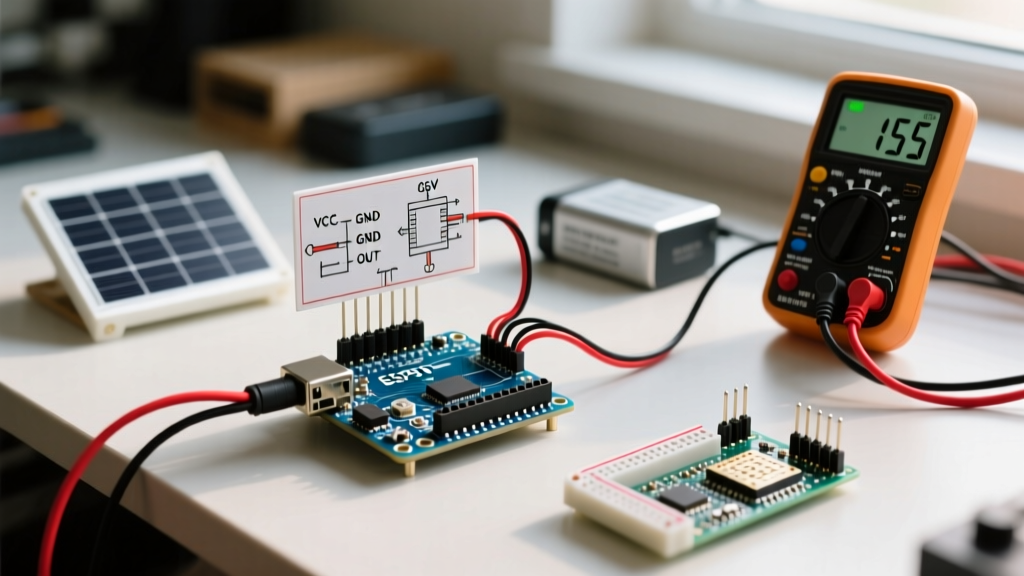
- VCC Pin: Connect to the Arduino 5V pin (ensures the module's op-amp/divider is referenced to the exact same rail as the ADC).
- GND Pin: Connect to Arduino GND. Critical: Ensure this shares a common ground with the battery's negative terminal.
- S (Signal) Pin: Connect to Arduino Analog Pin A0.
- + / - Terminals: Connect directly to the battery terminals or the BMS busbars.
Calibrated Code Implementation with Oversampling
Standard single-read ADC code is highly susceptible to noise. The code below implements a 16-sample oversampling technique to smooth out transient spikes, alongside a calibration multiplier. In real-world testing, carbon film resistors on cheap modules rarely yield a perfect 5.0 divider ratio; they usually sit around 4.9 to 5.1.
const int analogInPin = A0;
float Vref = 5.00; // Measure your Arduino 5V pin with a multimeter and update this
float dividerRatio = 5.00; // Update after bench calibration

void setup() {
  Serial.begin(9600);
  analogReference(DEFAULT); // Tied to stabilized 5V rail
}

void loop() {
  long sum = 0;
  // 16x oversampling to reduce ADC noise floor
  for(int i = 0; i < 16; i++) {
    sum += analogRead(analogInPin);
    delay(2);
  }

  float avgADC = sum / 16.0;
  float voltageOut = (avgADC * Vref) / 1023.0;
  float batteryVoltage = voltageOut * dividerRatio;

  Serial.print("Battery Voltage: ");
  Serial.print(batteryVoltage, 2);
  Serial.println(" V");

  // Trigger low-voltage disconnect warning
  if(batteryVoltage < 11.80) {
    Serial.println("WARNING: Lead-Acid Sulfation Threshold Reached!");
  }

  delay(2000);
}
The Calibration Procedure
Never trust the hardcoded 5.0 multiplier. To calibrate your specific voltage sensor Arduino build:
- Connect a bench power supply set to exactly 12.00V to the sensor terminals.
- Measure the Arduino's 5V pin with a high-quality multimeter (e.g., Fluke 117) and update the
Vrefvariable. - Read the serial output. If it reads 11.85V, calculate the new ratio:
(12.00 / 11.85) * 5.0 = 5.063. Update thedividerRatiovariable.
Real-World Edge Cases and Failure Modes
1. Temperature Coefficient (Tempco) Drift
The generic blue 25V modules use cheap carbon film resistors with a temperature coefficient of roughly ±200 ppm/°C. If your solar enclosure experiences a 40°C temperature swing from winter night to summer afternoon, the resistance value will shift. For a 12V system, a 200 ppm shift across a 40°C delta results in a ~0.1V measurement drift. While acceptable for basic low-voltage alarms, this drift is unacceptable for precise state-of-charge (SoC) calculations. If you require high precision across wide temperature ranges, replace the module's resistors with 25 ppm/°C metal film alternatives, or switch to the INA219.
2. Wire Gauge Voltage Drop
Voltage is not uniform across a circuit carrying current. If your solar inverter is pulling 20A through 10 feet of 10 AWG wire, the voltage drop across the wire is approximately 0.2V. If your sensor is wired to the inverter terminals rather than the battery busbars, your Arduino will read 11.8V while the battery is actually sitting at 12.0V. Always wire the sensor directly to the battery terminals to measure the true electrochemical potential of the cells.
3. Ground Loop Noise
In systems with large DC-DC converters or MPPT charge controllers, high-frequency switching noise can infiltrate the ground plane. If your analog readings show a ±0.3V jitter, you likely have a ground loop. Solve this by routing the sensor's ground wire in a star-ground topology directly back to the Arduino's GND pin, avoiding shared ground paths with high-current motor or inverter loads.