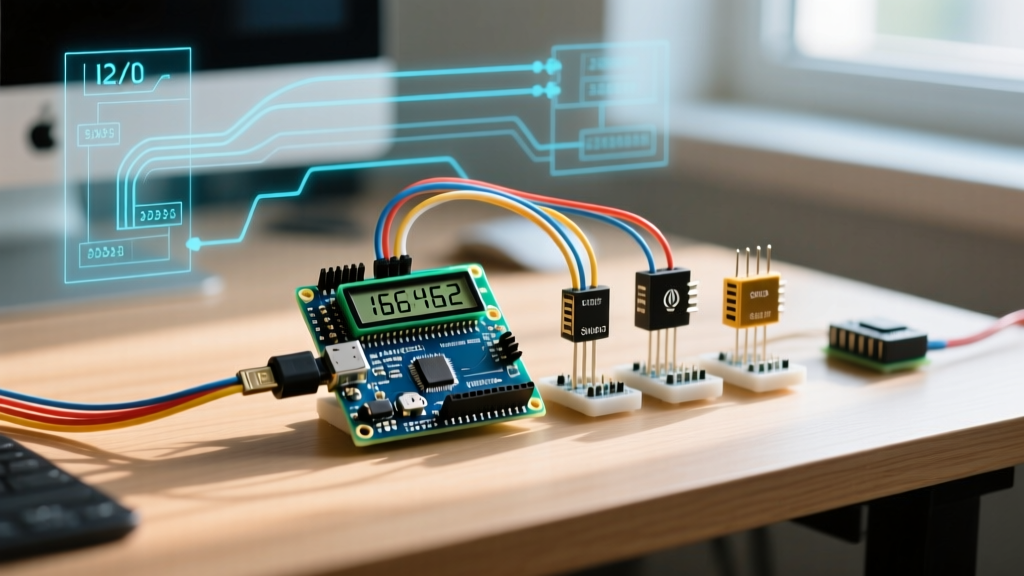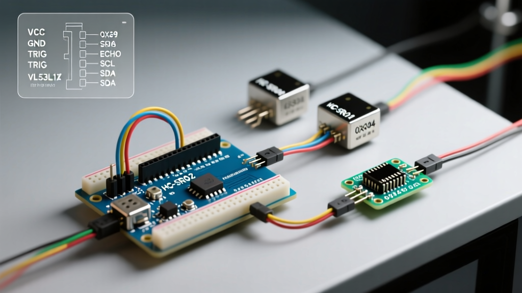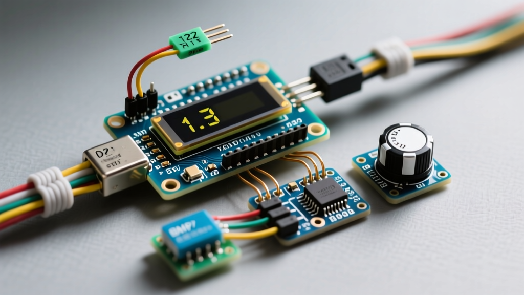

Connecting an Arduino and display module in isolation is a rite of passage for electronics hobbyists. However, when you scale up to a multi-peripheral setup—adding environmental sensors, real-time clocks, and motor controllers—the system often becomes unstable. Screens flicker, sensors return null values, and the microcontroller spontaneously resets. These failures rarely stem from flawed code; instead, they are the result of I2C address collisions, SPI bus contention, logic level mismatches, and power rail brownouts.
In this comprehensive guide, we dissect the electrical and architectural challenges of integrating an Arduino and display into a complex sensor array, providing actionable wiring strategies and hardware solutions for 2026.
The I2C Bottleneck: Address Collisions and Multiplexing
The I2C bus is the default communication protocol for most OLED displays and environmental sensors. The primary limitation of I2C in multi-peripheral setups is address space. Many popular components share hardcoded I2C addresses, leading to immediate bus collisions when wired to the same SDA and SCL lines.
Common I2C Address Conflicts
| Component Type | Model / Part Number | Default I2C Address | Alternative Address |
|---|---|---|---|
| OLED Display | SSD1306 (128x64) | 0x3C | 0x3D (via resistor mod) |
| OLED Display | SH1106 (128x64) | 0x3C | None |
| Temp/Humidity | BME280 | 0x76 | 0x77 |
| Temp/Humidity | AHT20 | 0x38 | None |
| RTC Module | DS3231 | 0x68 | None |
If your design requires two SSD1306 displays, or an AHT20 sensor alongside an OLED, you will hit a wall. According to the Adafruit I2C Address Master List, over 30% of common maker peripherals occupy the 0x30–0x40 hex range.
The Multiplexer Solution: TCA9548A
To resolve this, integrate a TCA9548A I2C Multiplexer (priced around $6.50 in 2026). This IC acts as a digital switch, allowing your Arduino to route I2C traffic to up to eight separate sub-buses. You can place an SSD1306 on sub-bus 0, and an AHT20 on sub-bus 1, completely bypassing address conflicts. When wiring the TCA9548A, ensure each sub-bus has its own 4.7kΩ pull-up resistors to maintain signal integrity across the switches.
SPI Bus Sharing for High-Resolution TFTs
When using higher-resolution color displays like the ST7789 or ILI9341 (common in 1.3-inch to 2.8-inch TFT modules), I2C lacks the bandwidth required for acceptable refresh rates. These displays utilize the SPI bus. Sharing the SPI bus with other peripherals (like an SD card module or an SPI DAC) requires strict adherence to Chip Select (CS) protocols.
Expert Insight: Never rely on software-defined (bit-banged) SPI for TFT displays in a multi-peripheral setup. Hardware SPI on the Arduino Uno (pins 11, 12, 13) or Nano is mandatory to achieve the 24MHz+ clock speeds required for smooth UI rendering. Consult the official Arduino SPI documentation to verify your specific board's hardware SPI pinout.
Managing Chip Select (CS) and Data/Command (DC) Pins
While the MOSI, MISO, and SCK lines can be shared across all SPI devices, the CS (Chip Select) and DC (Data/Command) pins must be unique to the display. In a multi-peripheral setup, daisy-chaining CS lines or leaving them floating will cause the display to interpret SD card data as pixel commands, resulting in screen tearing or white noise.
- Display CS: Connect to a dedicated digital pin (e.g., D10).
- SD Card CS: Connect to a different dedicated pin (e.g., D4).
- DC Pin: Exclusive to the display (e.g., D8). This pin tells the display controller whether incoming SPI data is a command byte or a pixel color byte.
Logic Level Translation: The 3.3V vs 5V Reality
A critical failure mode in modern Arduino and display setups is logic level mismatching. Most high-performance TFT and OLED displays operate strictly at 3.3V logic. Standard Arduino boards (Uno R3, Nano, Mega 2560) output 5V on their digital and SPI/I2C pins.
Feeding 5V logic into a 3.3V display's SDA or MOSI line will degrade the display's internal CMOS gates over time, leading to permanent pixel burn-in or total controller death within a few weeks. While many hobbyists use resistor voltage dividers (e.g., 10kΩ and 20kΩ) to step down 5V to 3.3V, this fails at high SPI frequencies. The parasitic capacitance of the resistors and breadboard traces acts as a low-pass filter, rounding off the square wave edges at 24MHz and causing data corruption.
The Correct Approach: Active Level Shifters
For robust multi-peripheral designs, use an active bi-directional logic level converter like the Texas Instruments TXS0108E or the NXP PCA9306 (specifically for I2C). These ICs use MOSFET-based translation that maintains sharp signal edges up to 50MHz, ensuring your Arduino and display communicate flawlessly without degrading the hardware.
Power Budgeting and Brownout Prevention
Displays are power-hungry. When you combine an Arduino, a TFT display, and multiple sensors on a single breadboard, you inevitably hit the current limits of the onboard voltage regulators.
| Peripheral | Operating Voltage | Typical Current Draw | Peak Current Draw |
|---|---|---|---|
| Arduino Nano (ATmega328P) | 5V | 45 mA | 60 mA |
| 1.3' ST7789 TFT (Backlight On) | 3.3V / 5V | 60 mA | 85 mA |
| 128x64 OLED (All Pixels White) | 3.3V / 5V | 20 mA | 35 mA |
| SG90 Micro Servo | 5V | 10 mA (idle) | 700 mA (stall) |
Cheap Arduino clones often use counterfeit or undersized AMS1117-3.3 linear regulators. If your display and sensors draw more than 150mA combined from the 3.3V pin, the regulator will overheat and drop out, causing the Arduino to brownout and reset. Rule of thumb: Never power a TFT display backlight or servo motors directly from the Arduino's 5V or 3.3V pins. Use a dedicated buck converter (like the LM2596 or MP1584EN) fed directly from your main power supply to handle display and actuator loads.
Signal Integrity: Pull-Up Resistors and Bus Capacitance
I2C is an open-drain protocol. It requires pull-up resistors to pull the SDA and SCL lines high. In a multi-peripheral setup, every module you add (display, RTC, sensor) often includes its own onboard 4.7kΩ pull-up resistors. When wired in parallel, these resistances drop drastically.
For example, three modules with 4.7kΩ pull-ups result in an equivalent resistance of roughly 1.56kΩ. This creates a high current draw when the line is pulled low, potentially exceeding the 3mA sink limit of the ATmega328P's I/O pins and causing logic errors.
Furthermore, as outlined in the SparkFun I2C Tutorial, the I2C specification limits total bus capacitance to 400pF. Long ribbon cables and breadboard traces add parasitic capacitance (approx. 2-3pF per inch). If your wiring is too long, the signal edges become too slow for the Arduino to read. Solution: Remove the pull-up resistors from all but one module on the bus, or use a dedicated I2C bus buffer like the PCA9600 to drive long cable runs.
Troubleshooting Edge Cases and Failure Modes
When your multi-peripheral setup misbehaves, use this diagnostic checklist to isolate the fault:
- Display Flickers When Sensor Reads: The sensor is pulling too much current during its measurement cycle, causing a momentary voltage sag on the 3.3V rail. Add a 100µF decoupling capacitor across the VCC and GND pins of the display.
- Screen Shows 'Snow' or Static: SPI clock speed is too high for the current wiring length, or logic level shifting is missing. Drop the SPI clock in your code (e.g.,
SPI.beginTransaction(SPISettings(8000000, MSBFIRST, SPI_MODE0))) to test if signal integrity is the culprit. - Arduino Freezes Randomly: A motor or relay on the same power rail is generating Electromagnetic Interference (EMI) or back-EMF spikes. Optoisolate your relays and use flyback diodes across all inductive loads.
- I2C Scanner Finds Nothing: Check for a missing common ground. The GND of the Arduino, the display, and all external power supplies must be tied together to establish a common reference voltage.
Building a reliable multi-peripheral system with an Arduino and display requires moving beyond simple plug-and-play wiring. By managing bus capacitance, respecting logic level thresholds, and engineering a robust power delivery network, you can create commercial-grade DIY electronics that operate flawlessly in the real world.