
The Reality of Motor Control: Beyond the L298N
When transitioning from blinking LEDs to moving heavy physical objects, the most critical bottleneck in your robotics project is power delivery. A microcontroller's GPIO pins can only source about 20mA to 40mA—barely enough to light an LED, let alone spin a 12V DC gear motor drawing 5A under load. This is where a robust motor driver Arduino setup becomes mandatory. However, the hobbyist market is saturated with outdated solutions that fail spectacularly in real-world, high-torque applications.
Why Legacy Drivers Fail in Real-World Applications
For over a decade, the L298N dual H-bridge has been the default recommendation for beginners. While it is cheap and widely available, it relies on antiquated Bipolar Junction Transistor (BJT) Darlington pairs. According to the Arduino Motors Guide, understanding voltage drop is crucial for efficiency. The L298N suffers from a massive internal voltage drop of 2V to 3V at just 2A of current. If you feed it a 12V battery, your motor only receives 9V, and the remaining 3V is dissipated as pure heat, requiring massive heatsinks and drastically reducing your rover's battery life.
In 2026, modern MOSFET-based drivers have completely superseded these legacy chips, offering near-zero voltage drops, higher current capacities, and built-in protection circuitry. For a high-torque autonomous rover designed to traverse outdoor terrain, upgrading your motor driver Arduino architecture is not optional; it is a fundamental requirement for reliability.
Selecting the Right Motor Driver for Arduino Systems
Choosing the correct driver depends on your motor's stall current, operating voltage, and physical footprint. Below is a comparison of the three most reliable modern drivers used in professional and advanced hobbyist robotics.
| IC / Module | Max Continuous Current | RDS(on) / Voltage Drop | 2026 Avg Price | Best Real-World Application |
|---|---|---|---|---|
| Texas Instruments DRV8871 | 3.6A | ~0.45Ω (Low Drop) | $4.50 | Small actuators, robotic arms, 12V indoor rovers |
| Toshiba TB6612FNG | 1.2A (3.2A Peak) | 0.5V Drop | $6.00 | Micro-rovers, balancing robots, low-power N20 motors |
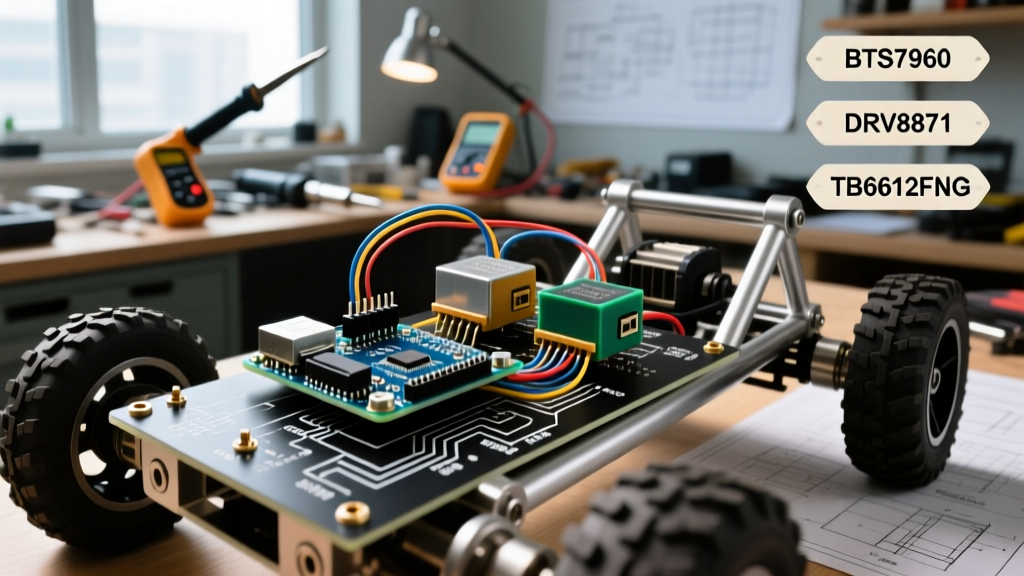
| Infineon BTS7960 (Module) | 27A (43A Peak) | Extremely Low mΩ | $14.00 | Heavy-duty outdoor rovers, e-bikes, high-torque winches |
Note: For deeper technical specifications on integrated H-bridges, refer to the Texas Instruments DRV8871 Datasheet, which outlines thermal shutdown and overcurrent protection thresholds.
Real-World Build: 12V High-Torque Autonomous Rover
For this guide, we are building a heavy-duty outdoor rover capable of carrying a 15kg payload over grass and gravel. We will use two 12V 100RPM high-torque DC gear motors (stall current: 12A each) and the BTS7960 motor driver module, controlled by an Arduino Mega 2560.
Bill of Materials and 2026 Cost Breakdown
- Microcontroller: Arduino Mega 2560 Rev3 ($28.00)
- Motor Driver: 2x BTS7960 43A High-Power Modules ($28.00 total)
- Motors: 2x 12V 100RPM High-Torque Planetary Gear Motors ($45.00 each)
- Power Supply: 12V 20Ah LiFePO4 Battery Pack with 30A BMS ($65.00)
- Wiring: 14 AWG Silicone Power Wire, 22 AWG Stranded Logic Wire ($15.00)
Wiring the BTS7960 to the Arduino Mega
The BTS7960 module consists of two separate half-bridges (one for forward, one for reverse) and includes optocouplers for logic isolation. Proper wiring is critical to prevent ground loops.
- Power Delivery: Connect the battery positive to the BTS7960
B+terminal and battery negative toB-using 14 AWG wire. Keep these wires as short as possible to minimize inductance. - Logic Power: Connect the Arduino 5V pin to the module's
VCCpin. Do not power the logic side from the motor battery directly. - Grounding (Star Topology): Connect the Arduino GND to the module's
GNDpin. Crucially, ensure the battery negative, motor negative, and Arduino ground all meet at a single physical star point to prevent ground bounce. - PWM & Direction: Connect Arduino Pin 4 to
R_EN(Right Enable), Pin 5 toR_PWM(Right Forward), and Pin 6 toL_PWM(Right Reverse). Repeat for the left motor on Pins 7, 8, and 9.
Code Implementation: PWM and Directional Logic
Controlling the BTS7960 requires sending a PWM signal to either the forward or reverse pin, while keeping the other pin LOW. However, default Arduino PWM frequencies introduce significant operational issues.
Pushing PWM to 20kHz for Silent Operation
By default, the Arduino Mega outputs PWM at approximately 490Hz. When applied to a DC motor, this frequency falls squarely within the human hearing range, causing a loud, high-pitched whine. Furthermore, low-frequency PWM can cause micro-vibrations that accelerate gear wear. By manipulating the hardware timers, we can push the PWM frequency to 20kHz, rendering it ultrasonic and silent.
// Set Timer 4 (Pins 6, 7, 8) to 20kHz Fast PWM
void setupHighFreqPWM() {
  pinMode(6, OUTPUT);
  pinMode(7, OUTPUT);
  pinMode(8, OUTPUT);

  TCCR4A = 0; // Clear control register A
  TCCR4B = 0; // Clear control register B

  // Set Fast PWM, non-inverting mode, prescaler = 1
  TCCR4A = _BV(COM4A1) | _BV(COM4B1) | _BV(COM4C1) | _BV(WGM41);
  TCCR4B = _BV(WGM43) | _BV(WGM42) | _BV(CS40);

  // Set TOP value for 20kHz (16MHz / 1 / 20kHz - 1 = 799)
  ICR4 = 799;
}

void driveMotor(int pwmPinFwd, int pwmPinRev, int speed) {
  if (speed >= 0) {
    analogWrite(pwmPinRev, 0);
    analogWrite(pwmPinFwd, speed);
  } else {
    analogWrite(pwmPinFwd, 0);
    analogWrite(pwmPinRev, -speed);
  }
}
Note: Changing Timer 4 will affect the delay() function if it relies on that specific timer, but on the Mega, delay() uses Timer 0, leaving Timer 4 safe for motor control.
Thermal Management and Edge Case Troubleshooting
Even with high-efficiency MOSFETs, real-world environments introduce electrical noise and thermal stress. Here are the most common failure modes encountered in heavy-duty motor driver Arduino builds and how to solve them.
The Ground Loop Reset Issue
Symptom: The moment the rover encounters an obstacle and the motors stall (drawing peak current), the Arduino Mega randomly resets or the LCD display scrambles.
Cause: Ground bounce. When 20A flows through the ground wire, the wire's inherent resistance creates a voltage differential. The Arduino's ground reference spikes above the motor driver's ground reference, causing a brownout.
Solution: Implement a star-ground topology as mentioned above. Additionally, utilize the optocouplers built into the BTS7960 module by removing the jumper that ties the logic ground to the power ground, and power the Arduino from a separate 5V buck converter referenced only to the logic ground.
Inductive Kickback and Snubber Networks
Expert Warning: DC motors are massive inductors. When you abruptly cut power via the MOSFETs, the collapsing magnetic field generates a reverse voltage spike (V = L * di/dt) that can easily exceed 60V, instantly punching through the BTS7960's internal diodes and destroying the chip.
While premium modules include Schottky flyback diodes, many cheap 2026 marketplace clones omit them to save $0.10 per unit. Always verify the presence of diodes across the output terminals. For extreme reliability, solder a 0.1µF ceramic capacitor and a 100Ω 2W resistor in series (a snubber network) directly across the motor terminals to absorb high-frequency ringing.
Advanced Telemetry: Reading Motor Current
A major advantage of the BTS7960 module over basic drivers like the Pololu TB6612FNG Motor Driver Carrier is the inclusion of current sensing pins (R_IS and L_IS). These pins output an analog voltage proportional to the motor's current draw.
By connecting R_IS to an Arduino analog pin (e.g., A0), you can implement real-time stall detection. If the analog reading spikes above a predefined threshold (e.g., 800 out of 1023), your code can instantly cut PWM to prevent motor burnout or trigger an evasive maneuver. This closed-loop feedback transforms a dumb motor system into an intelligent, self-protecting drivetrain, which is the hallmark of professional-grade robotics engineering.