
Beyond the Clap Sensor: Why the MAX9814 Matters
When makers first explore audio processing, they typically reach for the ubiquitous KY-038 or LM393 sound sensor modules. Priced at under $1.00, these digital-only boards are fine for detecting a hand clap or a door knock, but they are entirely useless for actual audio waveform analysis, FFT (Fast Fourier Transform), or voice recognition. To capture real analog sound waves, you need a dedicated microphone amplifier. Enter the Analog Devices MAX9814, a high-performance, low-noise microphone amplifier with Automatic Gain Control (AGC). In 2026, breakout boards featuring the MAX9814 remain the gold standard for analog sensor audio Arduino projects, typically costing between $4.50 and $7.00.
This datasheet explainer bypasses the superficial wiring diagrams found on basic hobby blogs. Instead, we will deconstruct the MAX9814 silicon architecture, decode its AGC timing parameters, and establish a robust, interrupt-driven ADC sampling strategy for AVR-based Arduino boards.
Datasheet Deconstruction: The MAX9814 Architecture
The MAX9814 is not merely an op-amp; it is a complete audio signal conditioning chain. Understanding its internal blocks is critical for preventing signal clipping and minimizing the noise floor.
1. The 1.25V DC Bias and AC Coupling
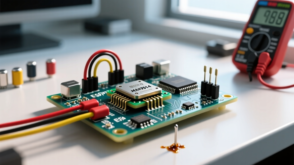
Microphones generate AC signals that swing positive and negative. However, the Arduino UNO's ATmega328P ADC can only read positive voltages (0V to 5V). The MAX9814 datasheet specifies an internal 1.25V DC bias (VBIAS) added to the output. This shifts the silent audio baseline to 1.25V, allowing the AC waveform to swing safely within the 0V–5V window without clipping the negative half-cycles. Never use a multimeter in DC mode to measure a 'silent' MAX9814 output and expect 0V; you will read approximately 1.25V.
2. Automatic Gain Control (AGC) Mechanics
The standout feature of the MAX9814 is its AGC, which dynamically adjusts the gain across three stages (40dB, 30dB, and 20dB) to prevent loud sounds from clipping while amplifying whispers. According to the official Analog Devices datasheet, the AGC behavior is governed by external capacitors on the ATTACK and RELEASE pins:
- Attack Time: How fast the IC reduces gain when a loud sound occurs. Default is typically 2ms.
- Release Time: How fast the IC restores maximum gain after the loud sound passes. Default is roughly 200ms.
- ARCTHR (AGC Threshold):strong> By default, this pin is tied to VDD, setting the threshold at -12dBFS. Pulling it lower adjusts the clipping point.
Expert Insight: If your project involves measuring sustained acoustic SPL (Sound Pressure Levels) rather than voice, the default 200ms release time will artificially compress your data. You must modify the physical release capacitor on the breakout board to slow down the AGC response, effectively turning it into a quasi-linear amplifier for measurement purposes.
Audio Sensor Comparison Matrix for Arduino
Before finalizing your PCB or breadboard layout, evaluate whether an analog sensor is truly what your microcontroller needs. Here is how the MAX9814 stacks up against modern alternatives in the current market.
| Module / IC | Interface | Best Use Case | MCU Compatibility | Approx. Price (2026) |
|---|---|---|---|---|
| MAX9814 | Analog (0-5V) | FFT, Envelope Detection, AVR ADC | Arduino UNO, Nano, Mega | $4.50 - $7.00 |
| INMP441 | I2S Digital | High-Fidelity Voice, Streaming, WiFi | ESP32, Teensy, Raspberry Pi Pico | $2.50 - $4.00 |
| KY-038 (LM393) | Digital (GPIO) | Clap Switches, Knock Detection | Any Microcontroller | $0.80 - $1.20 |
Precision Wiring and Decoupling Strategy
Audio circuits are notoriously susceptible to electromagnetic interference (EMI) and power supply noise. A common failure mode in sensor audio Arduino builds is a persistent 50Hz or 60Hz mains hum, or high-frequency whining from the Arduino's switching regulators.
The 'Star Ground' and Decoupling Protocol
- Power Supply: Feed the MAX9814 VCC from the Arduino's 5V pin, but place a 10µF tantalum capacitor and a 100nF ceramic capacitor in parallel across the VCC and GND pins as close to the module as possible.
- Grounding: Do not daisy-chain grounds. Run a dedicated ground wire from the MAX9814 GND pin directly to the Arduino's GND pin (Star Grounding).
- Analog Reference: By default, the Arduino uses the 5V USB rail as the ADC reference. USB power is noisy. For a lower noise floor, use the Arduino's internal 1.1V reference or an external precision voltage reference, adjusting your voltage divider accordingly.
For a deeper understanding of how the ATmega328P handles analog signals, consult the Arduino Analog Input Documentation, which details the multiplexer and sample-and-hold circuitry limitations.
Interrupt-Driven ADC Sampling (Code Strategy)
The most critical mistake beginners make is using analogRead() inside a standard loop() with delay(). The analogRead() function takes approximately 112 microseconds to execute. If you add any serial printing or math, your sampling rate drops unpredictably, violating the Nyquist-Shannon sampling theorem and causing severe aliasing.
Human voice ranges from 300Hz to 3.4kHz. To accurately capture a 4kHz signal, you must sample at a minimum of 8kHz (8,000 times per second). We achieve a stable 10kHz sampling rate using hardware timers.
Implementing the TimerOne Library
Using the Arduino TimerOne Library, we can trigger an Interrupt Service Routine (ISR) exactly every 100 microseconds.
#include <TimerOne.h>

const int micPin = A0;
volatile int audioSample;
volatile boolean sampleReady = false;

void setup() {
  Serial.begin(115200);
  // Initialize Timer1 for 100us interrupts (10kHz sampling rate)
  Timer1.initialize(100);
  Timer1.attachInterrupt(readAudio);
}

void readAudio() {
  audioSample = analogRead(micPin);
  sampleReady = true;
}

void loop() {
  if (sampleReady) {
    sampleReady = false;
    // Process the 10-bit sample (0-1023)
    // Subtract the 1.25V DC bias (approx 255 on a 5V/10-bit scale)
    int centeredSample = audioSample - 255;
    Serial.println(centeredSample);
  }
}
Note on ISR Execution: Keep the ISR as brief as possible. Only read the ADC and set a flag. Perform all heavy DSP math (like RMS calculations or FFT binning) inside the main loop() triggered by the flag.
Real-World Failure Modes and Troubleshooting
Even with perfect code, analog audio integration presents physical challenges. Here is how to diagnose the most common edge cases:
- Symptom: Output is stuck at 1023 or 0.
Diagnosis: The AGC has latched due to a continuous ultrasonic or high-SPL noise source in the room (like a CRT monitor flyback transformer or a failing LED driver). Fix: Mute the environment or physically shield the electret microphone capsule. - Symptom: Severe 60Hz buzz in the serial plotter.
Diagnosis: Ground loop or USB power noise. Fix: Power the Arduino via a linear regulator (like an LM7805) fed by a battery, completely isolating it from PC USB switching noise. - Symptom: High-frequency 'whine' overlaying the audio.
Diagnosis: The Arduino's 16MHz crystal oscillator or PWM pins are coupling into the analog trace. Fix: Keep the audio output wire away from digital pins 3, 5, 6, 9, 10, and 11, which handle hardware PWM.
Final Verdict
The MAX9814 remains an indispensable component for the sensor audio Arduino ecosystem. By respecting its 1.25V DC bias, properly configuring the AGC attack/release thresholds, and abandoning blocking delay() functions in favor of hardware timer interrupts, you elevate your project from a simple noise detector to a legitimate digital signal processing platform.